
Method and Means for Controlling a Robot

a robot and robot control technology, applied in the field of programmable robots, can solve the problems of inability to meet the needs of customers, difficult to understand the customer, and difficulty in displaying orientation for a person without the required experien

Pending Publication Date: 2013-09-05
UNIVERSAL ROBOT
View PDF25 Cites 14 Cited by
  • Summary
  • Abstract
  • Description
  • Claims
  • Application Information

AI Technical Summary

Benefits of technology

The patent describes a robot that has a system to control its movement based on the geometrical features it has stored. This means that the robot can be controlled to move its joints and perform different tasks using the information it has stored.

Problems solved by technology

A problem with such frames is that a certain level of mathematical knowledge is required in order to be able to define such coordinate systems and also that it takes a considerable time to carry out this task, even for a person skilled in the art of robot programming and installation.
Particularly the representation of orientation is complicated for a person who lacks the required experience to understand this problem.
The meaning of such and similar questions is very straight forward to an average costumer who intends to use a robot, for instance at various stations in a production plant, and it may seem annoying and incomprehensible to the customer to be told that there may not be a simple answer to such—relevant—questions.

Method used


Image

  • Method and Means for Controlling a Robot
  • Method and Means for Controlling a Robot

Examples


Embodiment Construction

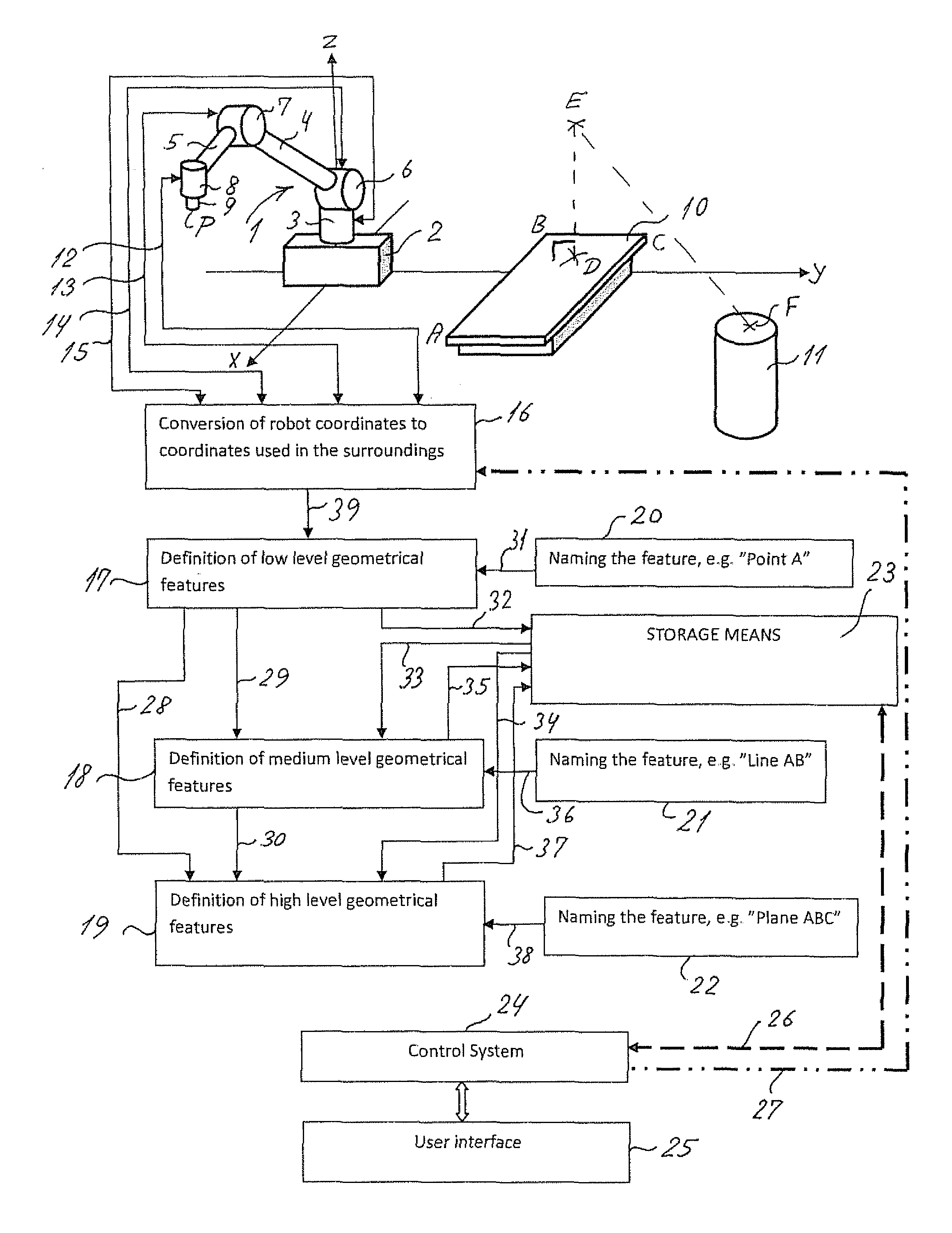
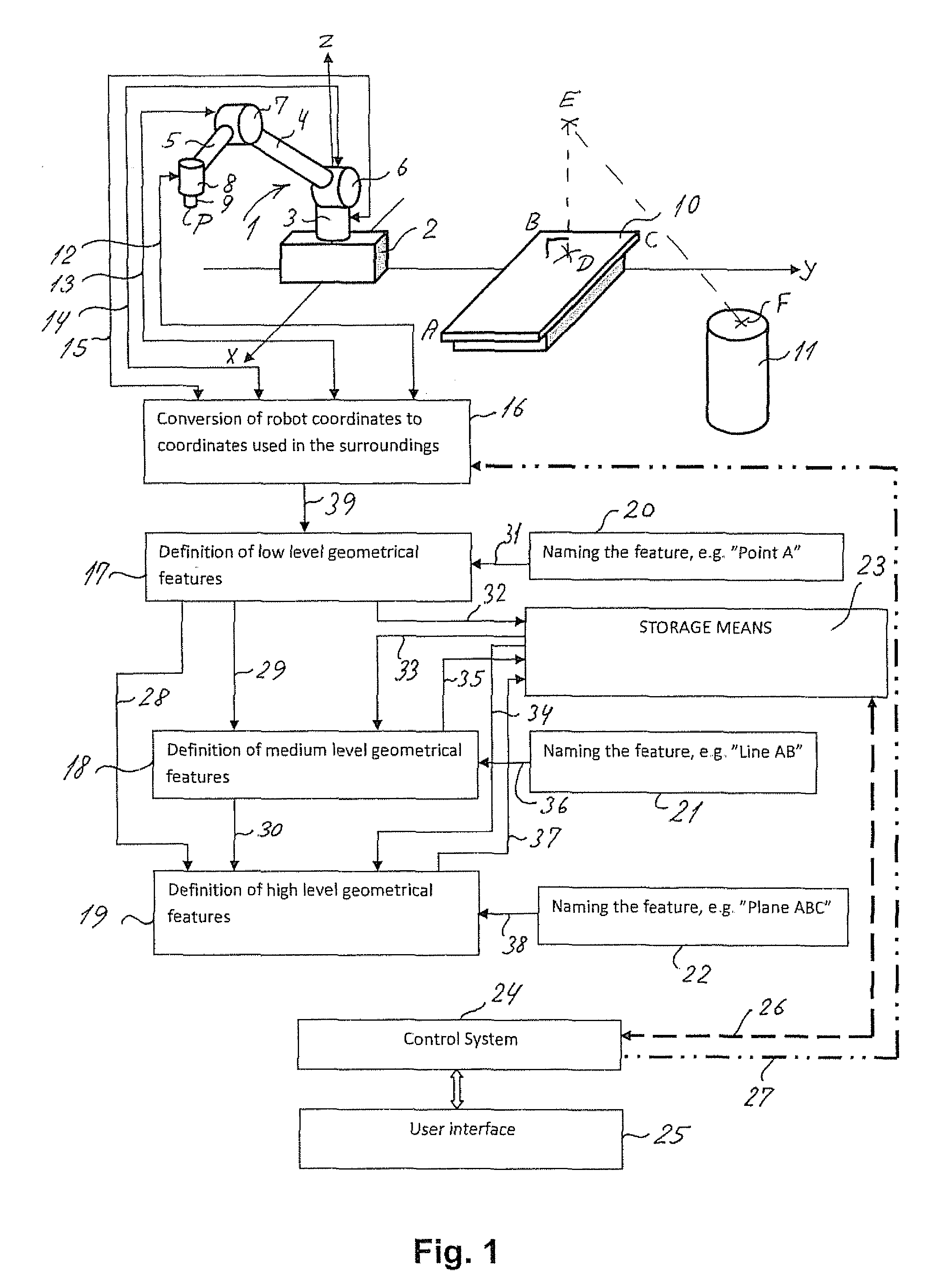
[0033]In the following there will be given a detailed description of a specific embodiment of the invention comprising a robot with encoders on each joint motor, wherein the robot can be taught a given position by manually moving a chosen part of the robot, such as the tool attachment member, or by jogging the robot to the different positions. The robot uses its joint encoders to measure the joint angles at the different positions, and the control software uses a kinematic model of the robot to translate these joint angles into a pose. The robot can then be programmed to move through these positions in sequence, where the robot is using the same encoders to reach the programmed poses, as was used to measure the poses.

[0034]With reference to FIG. 1 there is shown a schematic representation of a programmable robot according to an embodiment of the invention together with the main functional blocks used during definition of the geometrical features, programming of the robot and control...


PUM


Abstract

The present invention relates to a user friendly method for programming a robot, where the method comprises placing the robot at a given position P0 in the surroundings and using a portion or point P of the robot (for instance the point to which a tool is attached during use of the robot) to define one or more geometrical features relative to the surroundings of the robot and establishing a relationship between the geometrical features and first coordinates of a robot-related coordinate system, whereby the robot can subsequently be instructed to carry out movements of specified portions of the robot relative to said surroundings by reference to said one or more geometrical features. By these means it becomes easy for users that are not experts in robot programming to program and use the robot. The geometrical features can according to the invention be stored in storage means and used subsequently also in other settings than the specific setting in which the programming took place.

Description

TECHNICAL FIELD[0001]The present invention relates generally to the field of programmable robots and more specifically to programming methods for such robots.BACKGROUND OF THE INVENTION[0002]Customers who buy industrial robots generally want to be able to control or manipulate a robot, and to program the robot, relative to various objects and boundaries in the surroundings of the robot, such as machines, objects or blanks, fixtures, conveyers, pallets or vision systems. Traditionally this is done by defining “frames” (coordinate systems) that relate the internal coordinate system of the robot (the base coordinate system) to the relevant object's coordinate system. Reference can be made both to “tool coordinates” and to “base coordinates” of the robot.[0003]A problem with such frames is that a certain level of mathematical knowledge is required in order to be able to define such coordinate systems and also that it takes a considerable time to carry out this task, even for a person sk...

Claims


Application Information

Patent Timeline
Patent Type & Authority Applications(United States)
IPC IPC(8): G05D3/00
CPCG05B19/401Y10S901/27G05D3/00B25J9/1656G05B2219/36322G05B2219/36401
Inventor OSTERGAARD, ESBEN HALLUNDB.AE BUTTED.K
Owner UNIVERSAL ROBOT
Learn More