
Tire contour measurement data correction method and tire visual inspection device

a technology of contour measurement and measurement data, which is applied in the direction of closed circuit television systems, instruments, television systems, etc., can solve the problems of reducing productivity, long preparation time for measurement, and inability to accurately inspect the contour of a deflected tire, so as to correctly perform the visual inspection of a tire, the effect of lowering productivity

Active Publication Date: 2013-05-16
BRIDGESTONE CORP
View PDF2 Cites 8 Cited by
  • Summary
  • Abstract
  • Description
  • Claims
  • Application Information

AI Technical Summary

Benefits of technology

The present invention aims to correct contour deformation in tires caused by deflection during measuring. This helps to improve the accuracy of visual inspection of tires with deflection without needing any preparation work or reducing productivity.

Problems solved by technology

However, with the above-described prior-art methods, after the measurement data of the tire appearance shape (hereinafter referred to as “tire contour measurement data”) is obtained, since contour deformation caused by deflection is not corrected, the contour of a deflected tire cannot be inspected correctly.
Hence, if the tire appearance shape is measured by the above-described prior-art methods, the tire main body should be incorporated in the rim and air should be filled, and an internal pressure should be raised to a state where there is no deflection caused in the tire, and thus, there is a problem that preparation time for the measurement becomes long and productivity lowers.

Method used


Image

  • Tire contour measurement data correction method and tire visual inspection device
  • Tire contour measurement data correction method and tire visual inspection device
  • Tire contour measurement data correction method and tire visual inspection device

Examples


Embodiment Construction

[0024]An embodiment of the present invention will be described below by referring to the attached drawings.

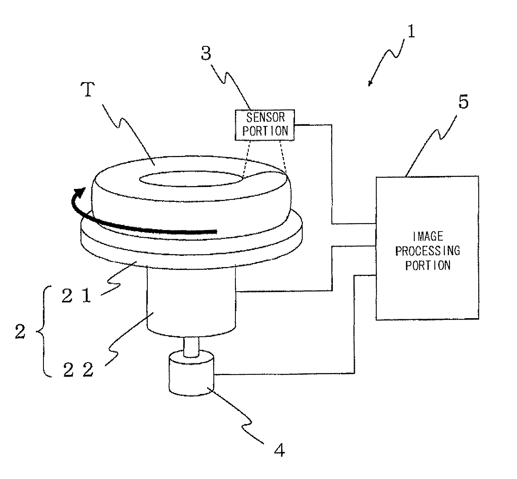
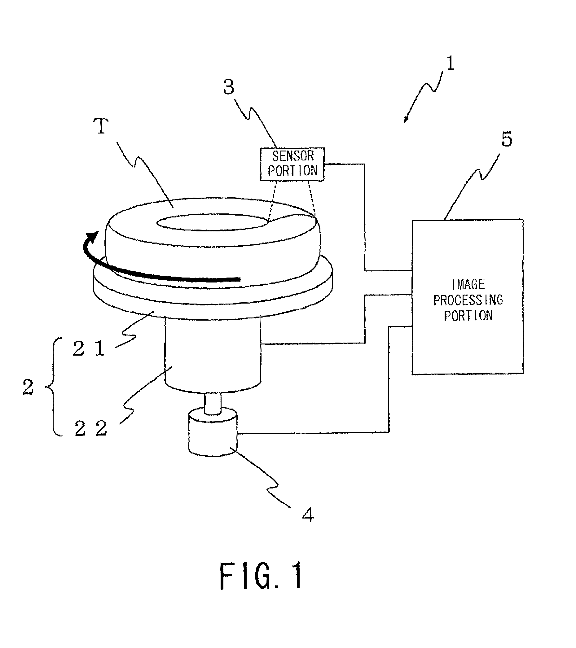
[0025]FIG. 1 is a block diagram illustrating a configuration of a tire visual inspection device according to one embodiment of the present invention.

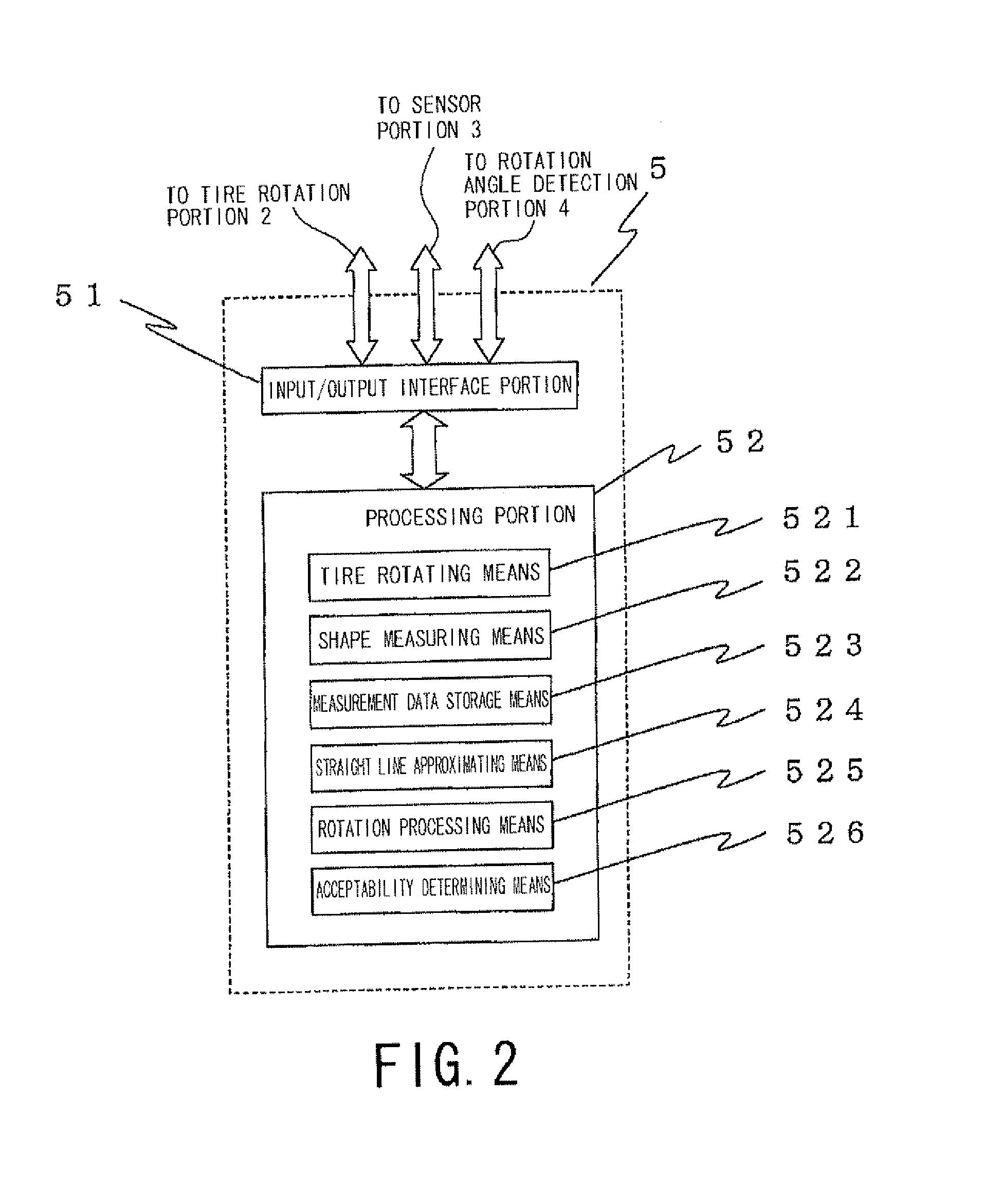
[0026]A tire visual inspection device 1 has a tire rotation portion 2 for rotating a tire T which is an inspection target by a stepping motor, for example, a sensor portion 3 for irradiating the tire T with line light and photographing an image of the line light, a rotation angle detection portion 4 for detecting a rotation angle of the tire rotation portion 2, and an image processing portion 5 for performing processing of the line light image photographed by the sensor portion 3 and the like.

[0027]The tire rotation portion 2 includes a disk-shaped tire placement base 21 for placing the tire T laterally, and a rotation driving portion 22 integrally attached to the lower end of the tire placement base 21 for rotating and driving the...


PUM


Abstract

In order to conduct a visual inspection correctly for a tire having deflection, contour deformation caused by the deflection of the tire is corrected with respect to tire contour measurement data. A tire contour measurement data correction method includes a step of obtaining a sidewall image in a tire radial direction at each certain rotation angle by a sensor portion while rotating a tire T to be inspected by a tire rotation portion, a step of dividing the sidewall image by a predetermined ratio by an image processing portion and approximating the sidewall image of each divided section by a straight line, a step of calculating an inclination angle in a horizontal direction of the approximate straight line, and a step of rotating the sidewall image of each divided section so that the inclination angle of the approximate straight line agrees with a predetermined angle determined for each divided section.

Description

TECHNICAL FIELD[0001]The present invention relates to a tire contour measurement data correction method for determining acceptability of tire appearance and a tire visual inspection device.BACKGROUND ART[0002]When acceptability of a tire shape is to be determined, a rubber material portion which is a tire main body portion constituting an outer peripheral portion is attached to a ring-shaped metal component (rim) constituting an inner peripheral portion of a tire, and after the inside is filled with air, an appearance shape of a tire side portion (sidewall), for example, is grasped and acceptability is determined.[0003]As such methods for grasping tire appearance shapes, a method using a three-dimensional shape measuring method called a light section method (See Patent Literature 1) and a method using an optical displacement sensor (See Patent Literature 2) are known.[0004]Here, the light section method is a method of irradiating a tire surface (sidewall, for example) along a radial...

Claims


Application Information

Patent Timeline
IPC IPC(8): H04N7/18
CPCH04N7/18G01B11/25G01B21/04
Inventor FUJII, TOMOHIKOMIZUTANI, AKINOBU
Owner BRIDGESTONE CORP
Learn More