
Technique for controlling access by a client entity to a service

Active Publication Date: 2012-05-10
FRANCE TELECOM SA
View PDF1 Cites 1 Cited by
  • Summary
  • Abstract
  • Description
  • Claims
  • Application Information

AI Technical Summary

Benefits of technology

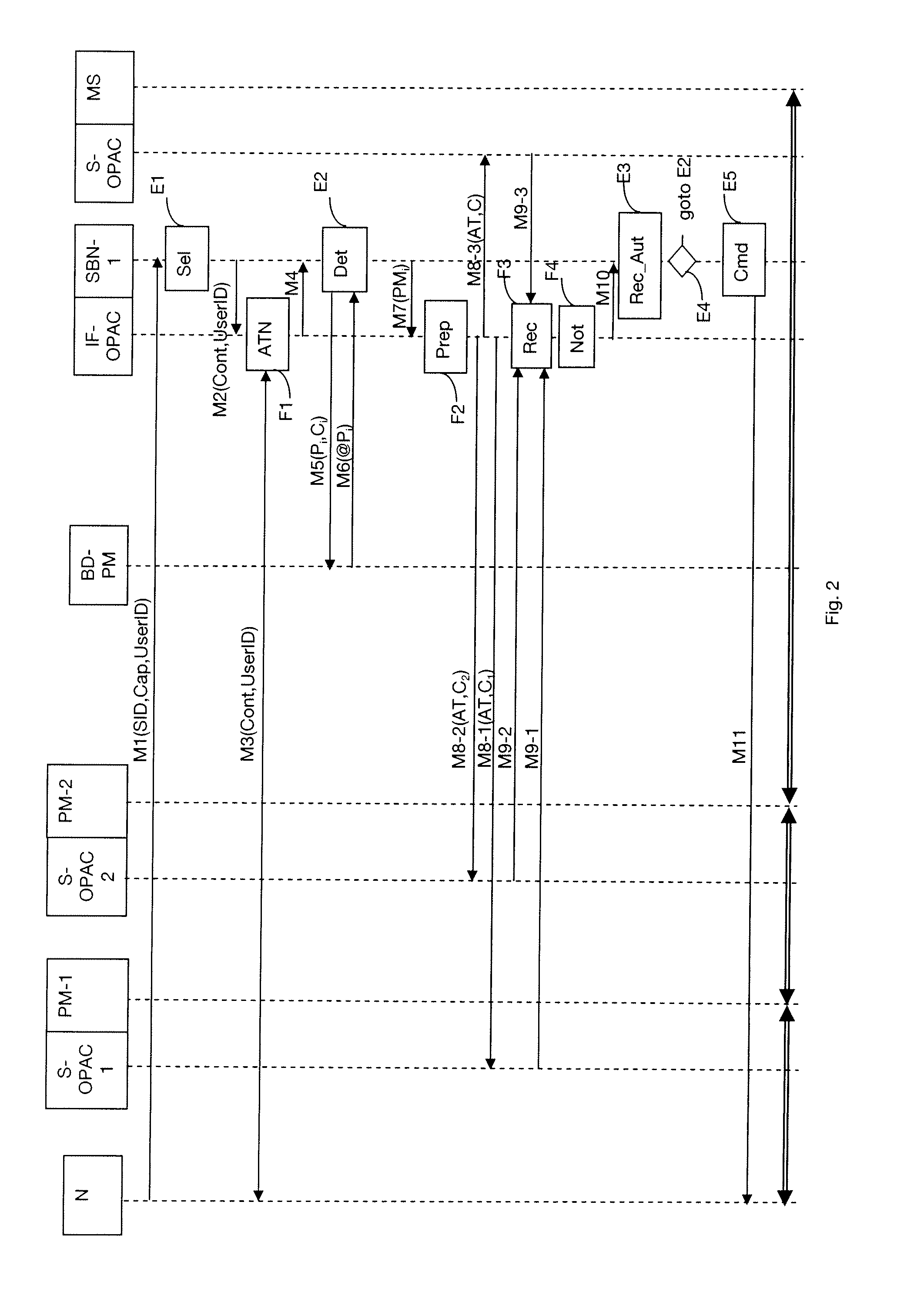
[0014]In order to implement the service to the client entity, a chain of individual functions is provided. The term “individual function” is used to mean, for example, a function of transcoding, metering, legal interception, watermarking, . . . . Such an individual function is described by input parameters, a function, and output parameters. The chain of individual functions then represents a sequence of processes to be implemented from a device supplyng the service and presenting certain output parameters to the client entity that presents certain input parameters. The processes are implemented by various processing modules in the communications network. The access control method relies on the various secondary access control devices delegating to the primary access control device the negotiation of the confidence relationship between them and the client entity. The primary access control device then verifies with the various access control devices associated with respective ones of the processing modules whether it is possible to use the processing module in order to implement the service for the particular client entity. This verification is performed using an “access token”. The term access token is used to mean proof of an agreement between two parties. In the present circumstances, it is an agreement between the client entity and the main access control device, representing the operator giving access to the service. Thus, if this is not possible for any of the processing modules, this particular chain of processing modules will not be reserved for the client entity. This avoids reserving resources in the communicat

Problems solved by technology

If access by the client entity to any one of the processing modules is not authorized, then it is not possible to supply the service to the client entity.
Furthermore, there are resources that have been reserved, but that end up not being used.
Thus, if this is not possible for any of the processing modules, this particular chain of processing modules will not be reserved for the client entity.
The negotiation by the client entity for access tokens giving access to the various secondary access control devices associated with the processing modules may give rise to heavy use of the resources in the underlying mobile network.
Furthermore, since controlling access to the chain of processing modules is performed as a preliminary operation, the client entity is not sent any positive response to a request for access to the service it has sent, in the event of it turning out in the end not to be possible for the client entity to access the resources of the communications network.

Method used


Image

  • Technique for controlling access by a client entity to a service
  • Technique for controlling access by a client entity to a service
  • Technique for controlling access by a client entity to a service

Examples


Embodiment Construction

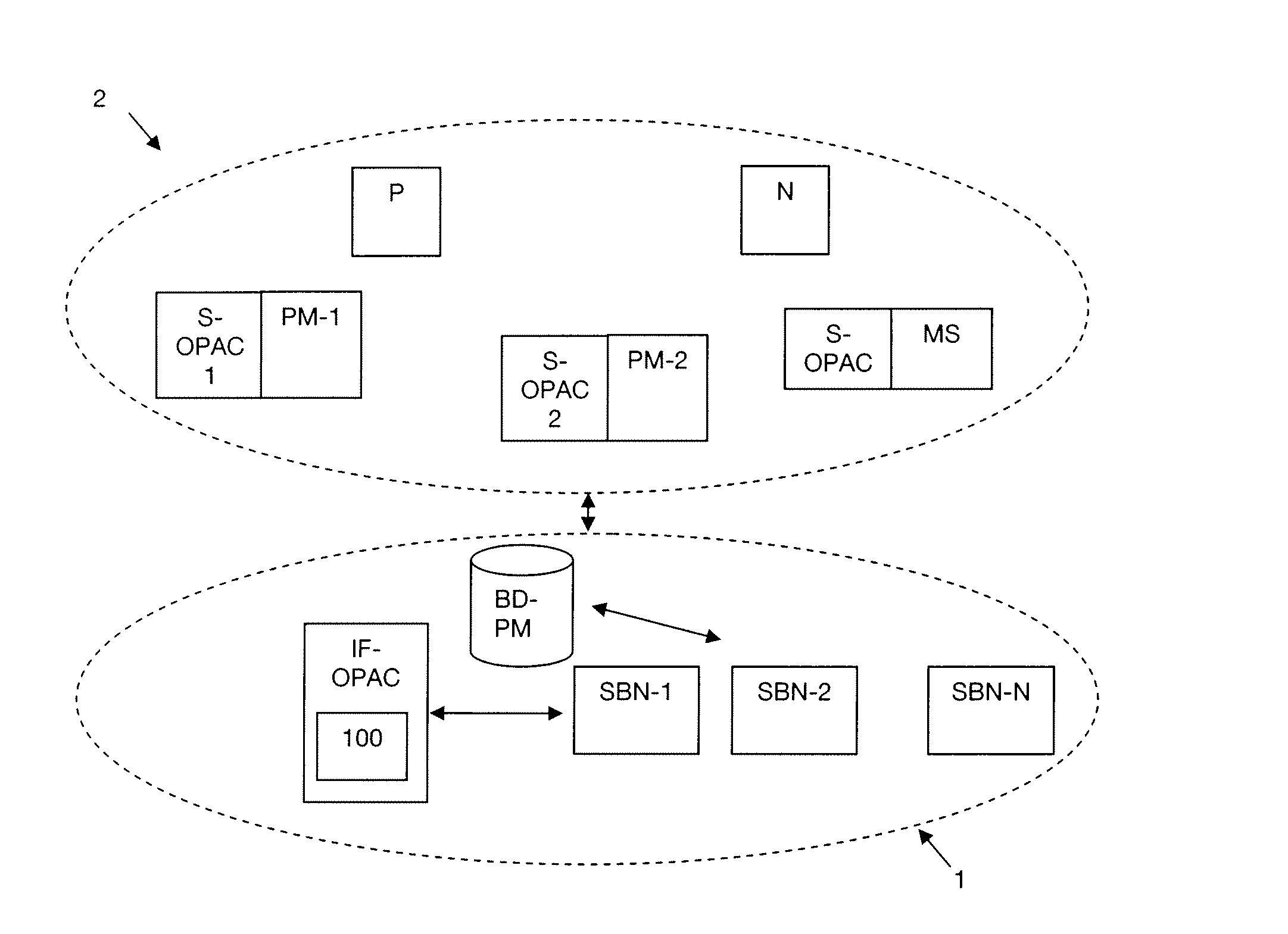
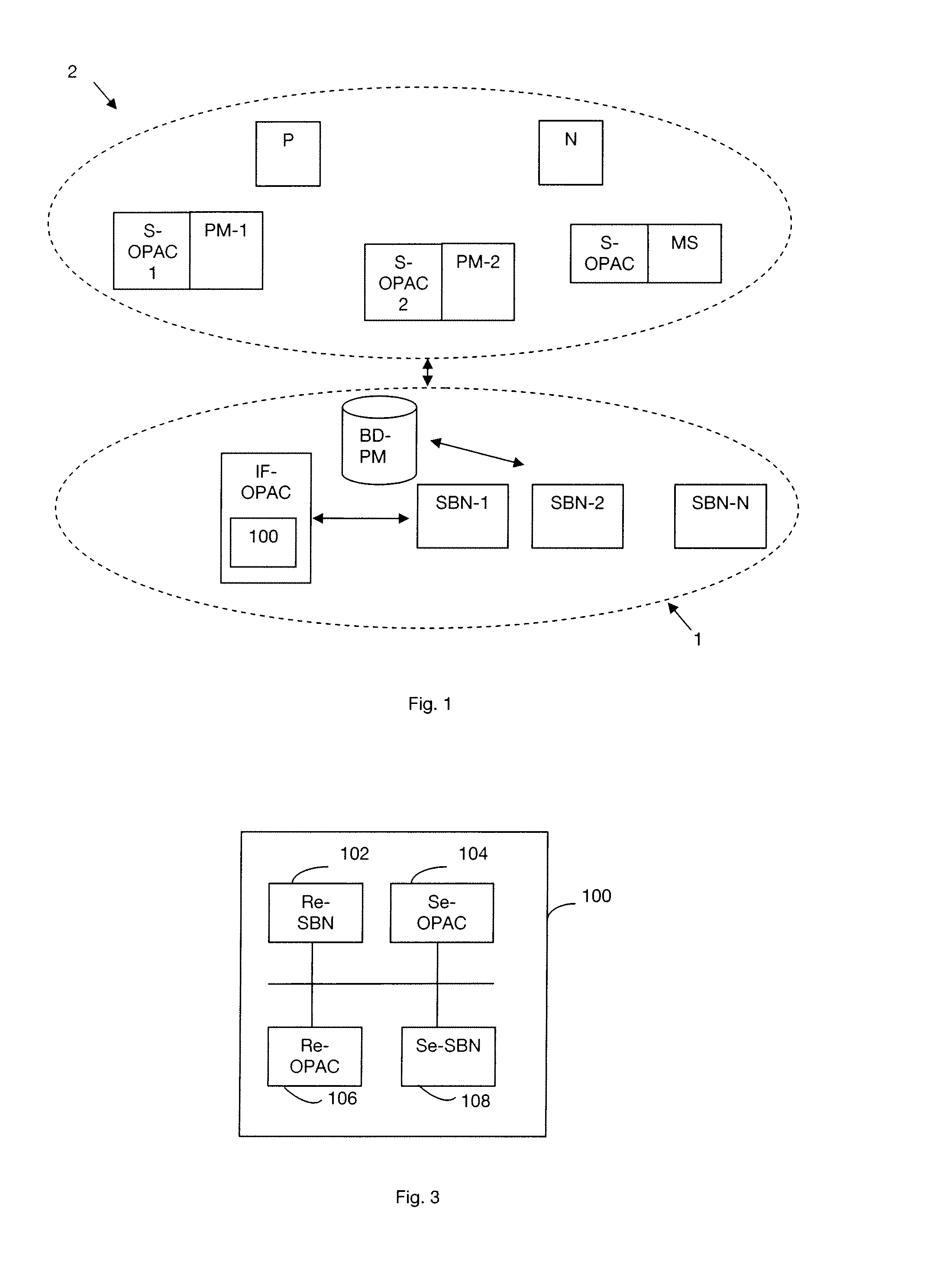
[0045]A system 1 for determining a chain of processing modules for providing a service to a client entity in a communications network 2 is shown diagrammatically in FIG. 1. An overlay network is a particular communications network. Below, the terms are used interchangeably. The system 1 comprises a plurality of service access nodes SBN-1, . . . , SBN-N for “service bootstrap node”. A terminal N is also shown in FIG. 1. Below the term “client entity” is used to designate the terminal N or the user U of the terminal N. In an embodiment of the invention, the system 1 also includes an access control entity referenced IF-OPAC for “interface overlay proxy access control”, which entity is administered by the operator giving access to the service. This access control entity IF-OPAC includes in particular a device 100 for controlling the access of a client entity to a service. The system 1 also includes a database processing module BD-PM that stores the processing modules made available by e...


PUM


Abstract

A technique of controlling access by a client entity to a service in a communications network. Processing modules are interconnected in the network in order to supply the service to the client entity. A processing module implements an individual function of a chain of individual functions associated with the service. The access method includes the following steps implemented by an access control device associated with an access node giving access to the service, the device being referred to as a main device: receiving a chain of processing modules from the access node; sending, to a secondary access control device associated with a processing module of the chain, a request to access the processing module under consideration, the request including an access token negotiated between the main device and the client entity; receiving a response to the access request from the secondary device; and notifying the access node of the response.

Description

CROSS-REFERENCE TO RELATED APPLICATIONS[0001]This Application is a Section 371 National Stage Application of International Application No. PCT / FR2010 / 051212, filed Jun. 17, 2010, which is incorporated by reference in its entirety and published as WO 2010 / 149899 on Dec. 29, 2010, not in English.STATEMENT REGARDING FEDERALLY SPONSORED RESEARCH OR DEVELOPMENT[0002]None.THE NAMES OF PARTIES TO A JOINT RESEARCH AGREEMENT[0003]None.FIELD OF THE DISCLOSURE[0004]The disclosure lies in the field of telecommunications and it relates in particular to a technique for controlling access by a client entity to a service.BACKGROUND OF THE DISCLOSURE[0005]In a communications network, a plurality of nodes may form an overlay network and thus be connected to one another. By way of example, the overlay network may be of the peer-to-peer type, referred to below as a P2P network. In such an overlay network, the nodes, referred to as “peers”, are interchangeable and possess capacities and responsibilities...

Claims


Application Information

Patent Timeline
IPC IPC(8): G06F21/20
CPCH04L63/0807H04L67/104H04L63/10
Inventor RADIER, BENOITSALAUN, MIKAELKLENK, ANDREASKLEIS, MICHAEL
Owner FRANCE TELECOM SA
Learn More