
Heat exchanger apparatus and methods of manufacturing cross reference

a technology of heat exchanger and cross reference, which is applied in the direction of lighting and heating apparatus, thermal-pv hybrid energy generation, laminated elements, etc., can solve the problems of large area thermal interface materials and large number of critical thermal interfaces, and achieve the effect of effective transfer, greater concentration and/or efficiency of solar cells, and effective transfer of hea

Inactive Publication Date: 2012-01-12
CYANTO CORP
View PDF1 Cites 19 Cited by
  • Summary
  • Abstract
  • Description
  • Claims
  • Application Information

AI Technical Summary

Benefits of technology

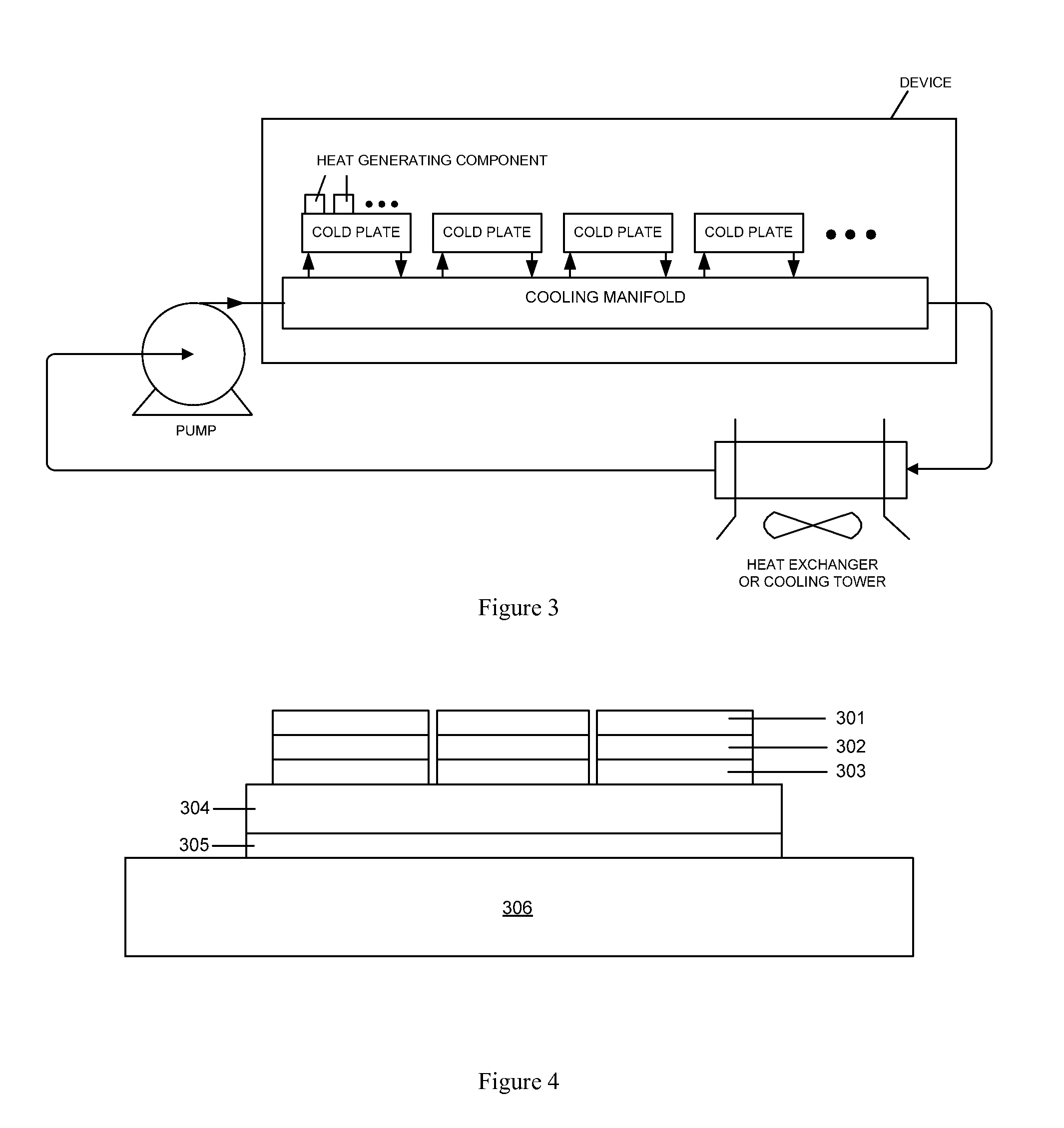
[0007]Another aspect of the invention provides for cold plate configurations and arrangements. Fluidic passages may be arranged through the cold plate such that heat may be effectively transferred from a solid structure to a fluid flowing within the cold plate or vice versa. A cold plate may be formed of layers that may include slots and / or holes that may form the fluidic passages. A cold plate may utilize three-dimensional fluid flow to effectively transfer heat.

Problems solved by technology

However, the use of such a dielectric layer requires a large number of critical thermal interfaces and large area thermal interface materials.

Method used


Image

  • Heat exchanger apparatus and methods of manufacturing cross reference
  • Heat exchanger apparatus and methods of manufacturing cross reference
  • Heat exchanger apparatus and methods of manufacturing cross reference

Examples


Embodiment Construction

[0024]While preferable embodiments of the invention have been shown and described herein, it will be obvious to those skilled in the art that such embodiments are provided by way of example only. Numerous variations, changes, and substitutions will now occur to those skilled in the art without departing from the invention. It should be understood that various alternatives to the embodiments of the invention described herein may be employed in practicing the invention.

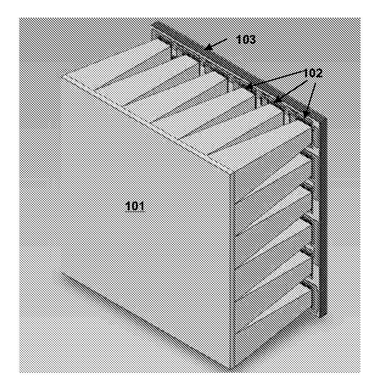
[0025]The invention provides cooling systems for a solar receiver. A solar receiver may be a photovoltaic receiver, such as a concentrated photovoltaic (CPV) receiver. A solar receiver may be mounted into a structure, such as a solar tower, a dish concentrator, or a multi-purpose structure. A CPV receiver may comprise a plurality of cells, one or more cold plate, and a cooling manifold. A receiver may comprise a plurality of modules (which may be referenced to in some instances as tiles). Modules may be arranged into an...


PUM


Abstract

The invention provides systems and methods for cooling semiconductor devices, such as those provided in concentrated photovoltaic (CPV) systems using a cold plate. The invention also provides using a material, such as a ceramic, to form that cold plate that matches or nearly matches the coefficient of thermal expansion (CTE) of a photovoltaic cell. Additionally, the cooling system may include fluidic passageways through which a fluid may flow, which may result in a transfer of heat between the fluid and the solid structure.

Description

CROSS REFERENCE[0001]This application claims the benefit of priority to U.S. Provisional Patent Application No. 61 / 116,637 filed on Nov. 20, 2008, which is incorporated herein by reference in its entirety.BACKGROUND OF THE INVENTION[0002]Solar cells have been used to convert solar energy into other forms of energy, such as electrical energy or thermal energy. Solar cells may be interconnected and may be bonded to a substrate to form a receiver. In some instances, concentrated photovoltaic (CPV) solar receivers may receive concentrated solar energy, which may be concentrated by optics and / or the reflection of solar energy from multiple reflective surfaces. In such situations, CPV receivers may generate electricity proportionally to the light flux they receive. Their efficiency is reduced as temperature increases. For example, solar cells that reach a temperature higher than 60 degrees Celsius lose between 10.5% and 17.5% of the power versus power generated at 25 degrees Celsius. A so...

Claims


Application Information

Patent Timeline
Patent Type & Authority Applications(United States)
IPC IPC(8): H01L31/052H01L31/024H05K7/20F28D15/00
CPCH01L23/473H01L31/052H01L2924/09701Y02E10/52H01L31/0547H01L31/0521H01L2924/0002H01L2924/00H02S40/22H02S40/44Y02E10/60F28F3/12
Inventor DONNELLY, SEAN M.
Owner CYANTO CORP
Learn More