
RF electrode for aesthetic and body shaping devices and method of using same

a technology of aesthetics and body shaping, which is applied in the field of aesthetic treatment and body shaping devices, can solve the problems of excessive heat induced by rf energy in the skin and underlying subcutaneous tissues, damage to the skin, and damage to the skin, and achieves the effects of reducing the risk of skin damage, reducing the safety of use, and improving the safety of us

Active Publication Date: 2010-01-21
SYNERON MEDICAL LTD
View PDF110 Cites 8 Cited by
  • Summary
  • Abstract
  • Description
  • Claims
  • Application Information

AI Technical Summary

Benefits of technology

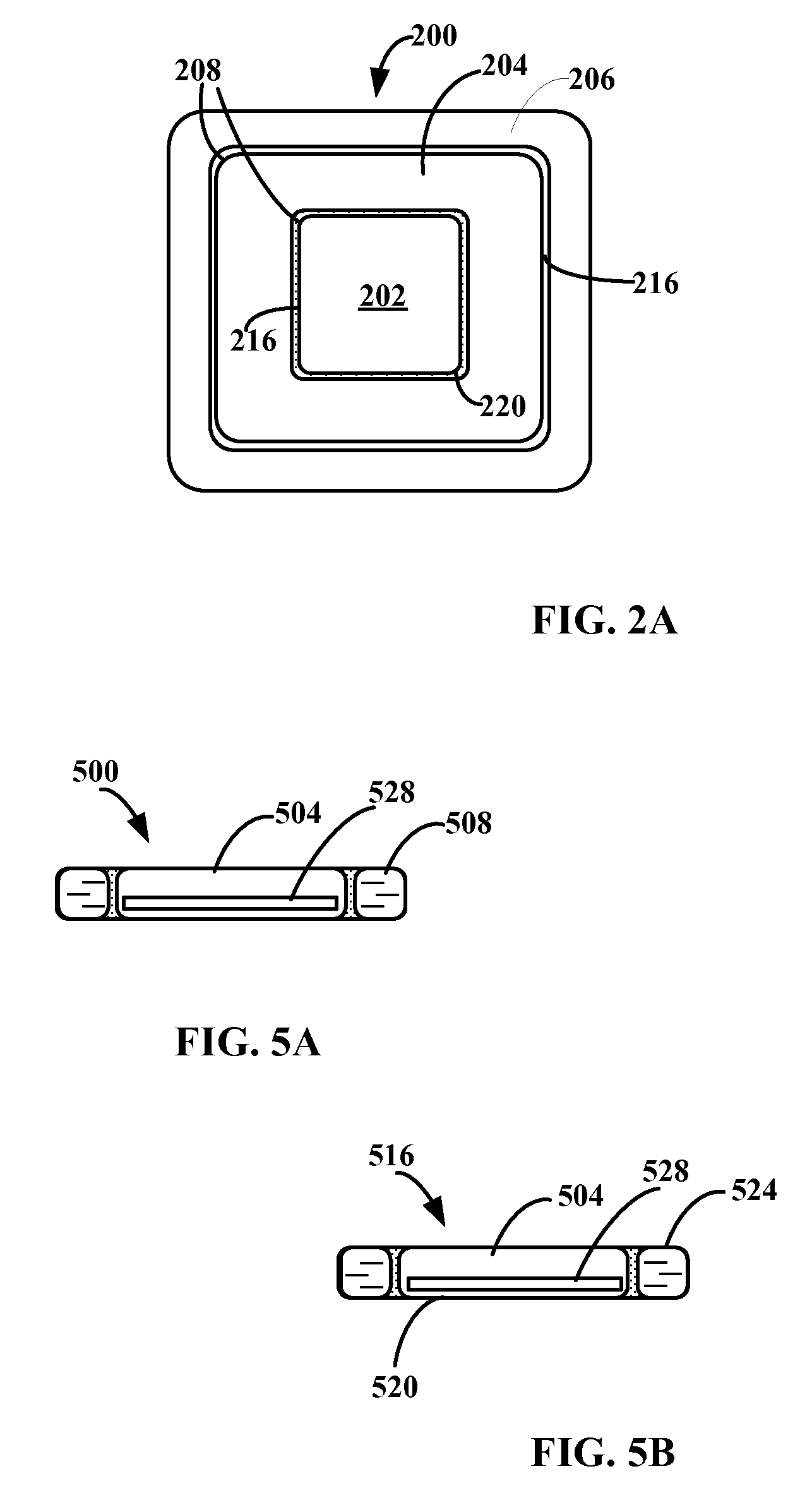
[0006]The present energy delivery device or electrode and method provide a solution for the overheating of the skin and underlying subcutaneous tissue coupled with the peripheral areas of the RF electrode energy delivery surface. The electrode energy delivery surface is segmented and the peripheral segments cooled thus creating a more balanced distribution of heat over the RF electrode energy delivery surface coupled with the skin. Advantageously, this enables safe and effective aesthetic procedures or treatment and body shaping. The central segment of the electrode may optionally be heated to reduce the treatment energy losses.GLOSSARY

Problems solved by technology

The heat induced in the skin and underlying subcutaneous tissues by the RF energy is not distributed in a balanced way across the electrode surface coupled with the skin, especially in the places where the skin does not form a good contact across the whole surface of the electrode.
In many situations, the temperature of the hot spots is high enough to damage the skin.
The rounded edges and corners have, to some extent, mitigated the heating effect, but the skin segments that are adjacent to the electrodes are still excessively heated by the RF.
Because of this uneven RF energy distribution across the electrode, achieving an effective treatment RF energy level across the electrode and in particular at the center portion of the electrode energy delivery surface, results in excessive heating at the energy delivery surface periphery and corners.
This causes undesired pain and possible damage to the skin and underlying subcutaneous tissue coupled with these peripheral areas and corners.
This phenomenon precludes achieving a sufficiently high, but safe level of energy that can be coupled to the skin through the RF electrode.

Method used


Image

  • RF electrode for aesthetic and body shaping devices and method of using same
  • RF electrode for aesthetic and body shaping devices and method of using same
  • RF electrode for aesthetic and body shaping devices and method of using same

Examples


Embodiment Construction

[0022]In the following detailed description, reference is made to the accompanying drawings that form a part hereof and wherein like reference numerals denote like elements through the several views.

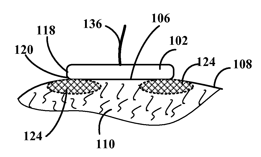
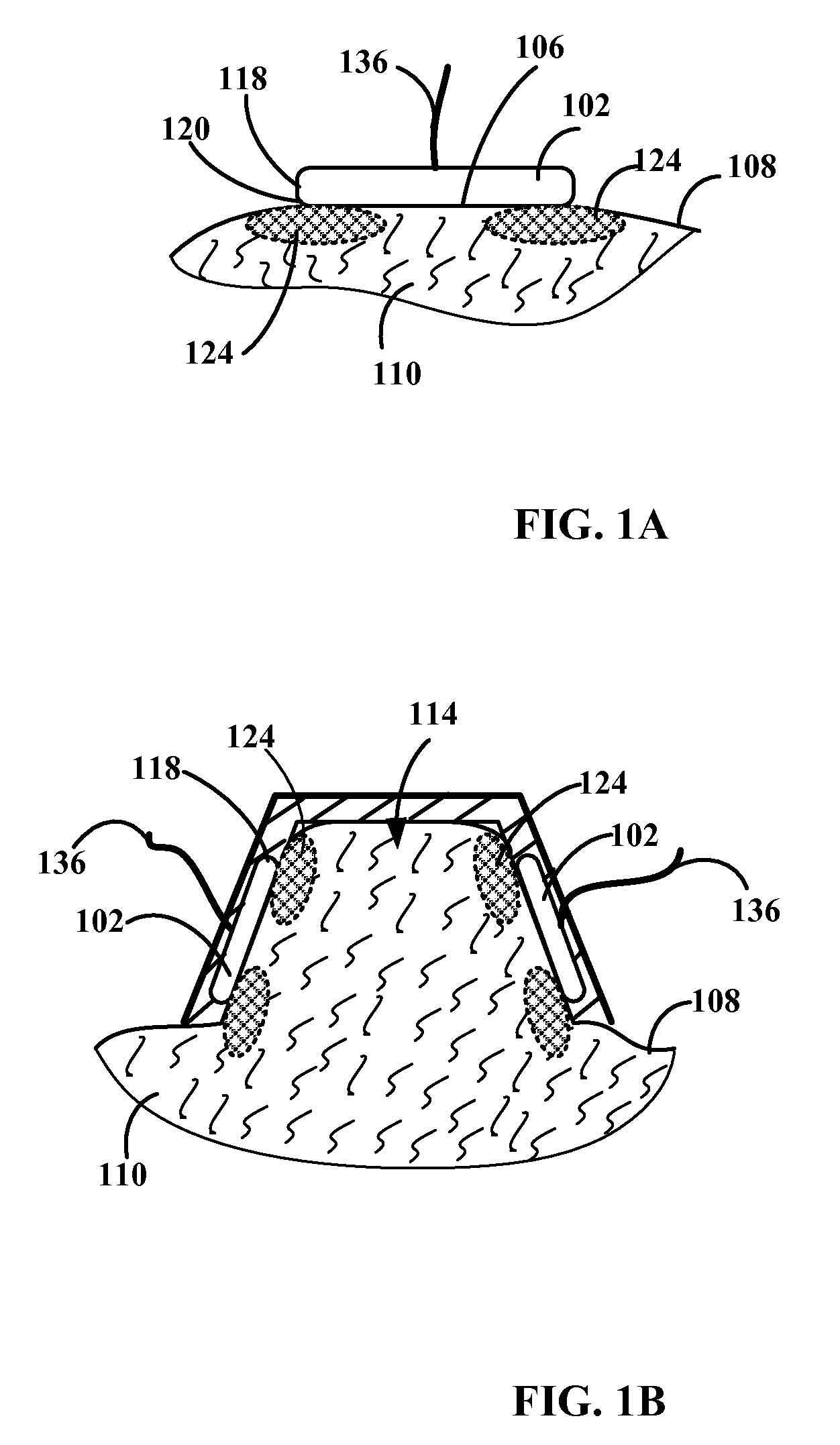
[0023]FIGS. 1A and 1B are schematic illustrations of the skin overheating effect by the periphery of a conventional (one of a pair) RF electrode. FIG. 1A schematically illustrates the skin overheating effect caused by a non-segmented RF electrode 102. Electrode 102 has a single-segment energy delivery surface 106 coupled through the surface of skin 108 to a volume of underlying subcutaneous tissue 110. For the simplicity of explanation the second or return electrode is not shown. Electrode 102 is applied to a segment of skin 108 or to a skin protrusion 114 (see FIG. 1B) formed by any known protrusion forming methods. For example, the United States Provisional Application for Patent assigned Ser. No 61 / 081,110 and assigned to the same assignee as this present disclosure and incorporated h...


PUM


Abstract

A segmented RF electrode with one central segment delivering the treatment energy and at least one peripheral segment arranged around the perimeter of the central segment and a temperature control element communicating with the peripheral segment. The electrode is incorporated into an applicator for aesthetic and other skin treatments.

Description

CROSS-REFERENCE TO RELATED APPLICATIONS[0001]This application is related to the United States Provisional Application for Patent assigned Ser. No. 61 / 081,110, which is hereby incorporated by reference.TECHNICAL FIELD[0002]The device and method relate to the field of aesthetic treatment and body shaping devices and more specifically to the use of a cooled RF electrode in aesthetic and body shaping devices.BACKGROUND[0003]The practice of using heat energy for aesthetic treatment and body shaping is known in the art. Heating of the skin and the underlying tissues over certain temperatures or temperature ranges results in tissue shrinkage and produces a desired aesthetic effect. The application of RF energy is one of the methods of heating the skin and underlying tissues.[0004]Aesthetic and / or body shaping treatment is administered using an applicator coupled with an RF electrode or energy delivery device connected to a source of RF. The electrode typically has an RF energy delivery sur...

Claims


Application Information

Patent Timeline
IPC IPC(8): A61B18/18
CPCA61B18/14A61B2017/00057A61B2017/308A61B2017/00084A61B2018/00452A61N7/00A61B2018/00011
Inventor ROSENBERG, AVNER
Owner SYNERON MEDICAL LTD
Learn More