
USB hub structure

a technology of usb hub and hub structure, which is applied in the direction of flexible lead accommodation, coupling device connection, instruments, etc., can solve the problems of shortening the use life of usb hub structure, and speeding up metal oxidization, so as to shorten the use life and speed up metal oxidization

Inactive Publication Date: 2006-10-12
YU TA LUNG
View PDF8 Cites 32 Cited by
  • Summary
  • Abstract
  • Description
  • Claims
  • Application Information

AI Technical Summary

Benefits of technology

[0010] A uplink port and a downlink port extended outside of a main body of a USB hub according to the present invention are capable of being engaged with each other and integrated at one side of the main body on which a plurality of downlink ports are disposed so as to protect the downlink ports on the side of the main body to prevent them from being influenced by dust collection or air pollution that speeds up the metal oxidization so as to shorten the use life, from causing a malfunction owing to the dust collection or being deformed to lose the function owing to the collision with outside stuff so that the hub entirety looks neat.
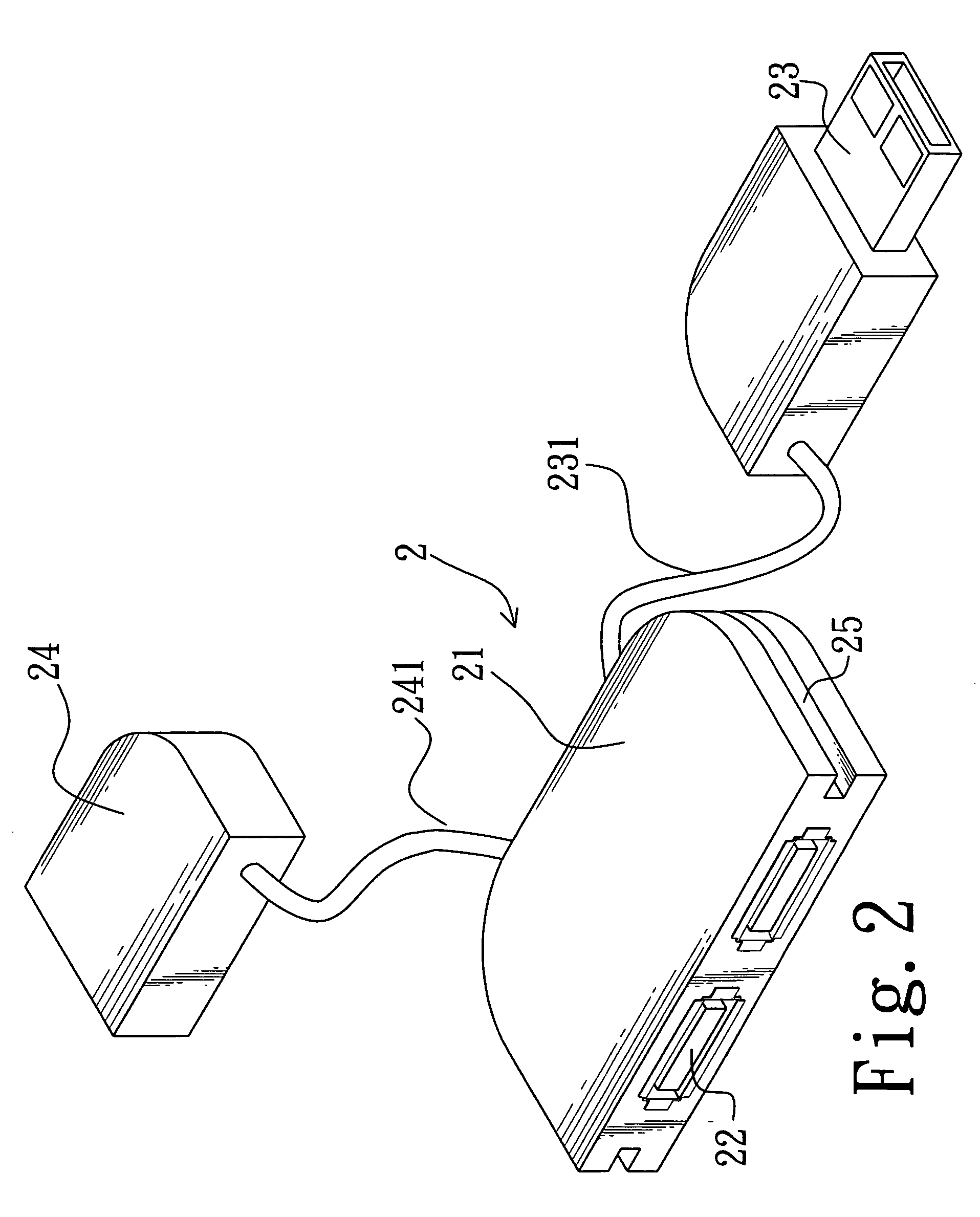
[0011] A cable accepting groove is disposed on the flank sides of a main body of a USB hub according to the present invention for accepting cables used for respectively connecting a uplink port and a downlink port extended outside of the main body with the main body to ensure that the uplink port and the downlink port extended outside of the main body are accurately engaged with each other and fixedly integrated without being displaced at one side of the main body on which a plurality of downlink ports are disposed. Further, because the cables for respectively connecting the uplink port and the downlink port extended outside of the main body with the main body are placed in the accepting groove, the cables can be protected from collision with outside stuff to avoid damage.

Problems solved by technology

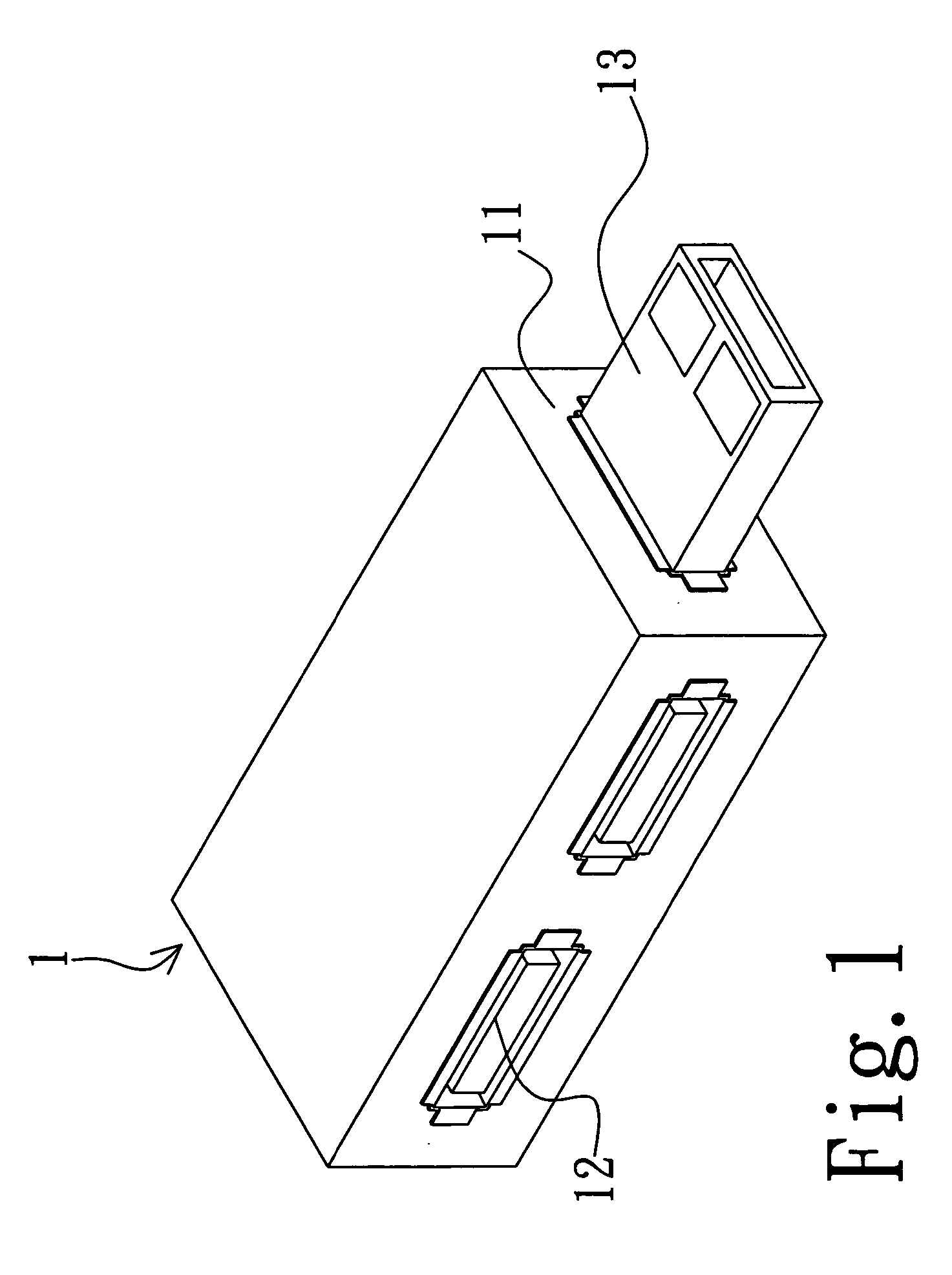
Furthermore, the metal oxidization is speeded up to shorten the use life of the USB hub structure owing to outdoor dust and air pollution, the malfunction of the hub is caused owing to the collection of dust or the deformation of the downlink ports 12 or / and uplink port 13 is caused to lose the function owing to the collision when the USB hub 11 is carried outside.

Method used


Image

  • USB hub structure
  • USB hub structure
  • USB hub structure

Examples


Embodiment Construction

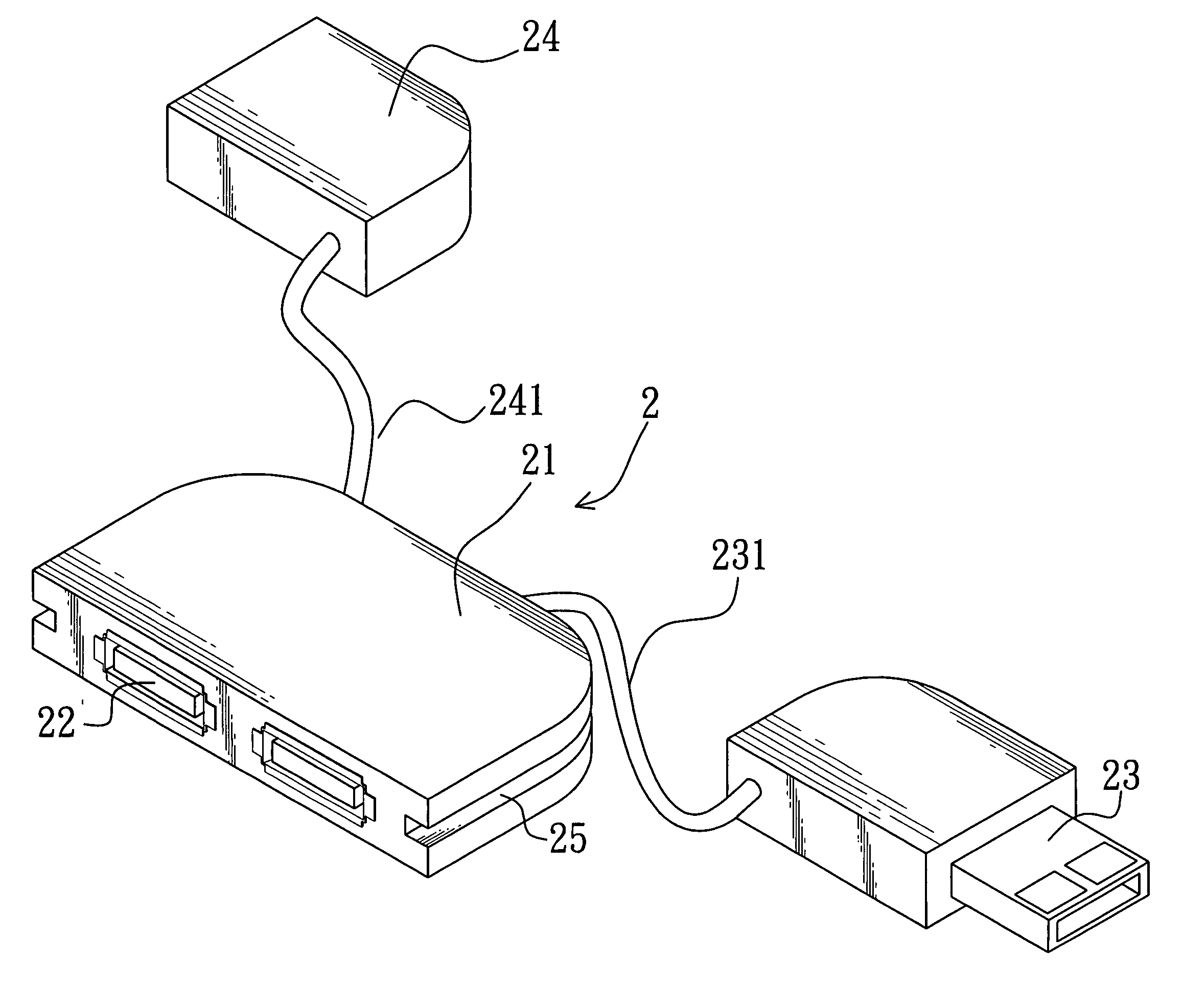
[0017] Please refer to FIG. 2. FIG. 2 is a prospective view showing a USB structure of a preferred embodiment of the present invention. A USB hub structure 2 comprises a main body 21, a plurality of downlink ports 22 disposed on the main body 21 and used for connecting computer peripheral electric equipments, a uplink port 23 used for connecting to a computer mainframe, a cable 231 for connecting the main body 21 with the uplink port 23, a downlink port extended outside of the main body 21 for connecting to a computer peripheral electric equipment, a cable 241 for connecting the main body 21 with the downlink port 24 and a cable accepting groove 25 disposed at the flank sides of the main body 21 and used for accepting the cables 231 and 241.

[0018] Please refer to FIG. 3. FIG. 3 is a schematic view showing a use state of a USB hub structure according to the present invention. When the USB hub structure 2 is in use, the main body 21 is connected to the uplink port 23 through the cabl...


PUM


Abstract

A USB hub structure comprises a main body, a plurality of downlink ports disposed directly on the main body, a uplink port connected to the main body with a cable and a downlink port extended outside of the main body and connected to the main body with another cable. Whereby, the uplink port and the downlink port extended outside of the main body can be engaged with each other and integrated at one side on which the downlink ports are disposed so that the structure is convenient to be carried and the downlink ports disposed on the main body can be protected.

Description

BACKGROUND OF THE INVENTION [0001] 1. Field of the Invention [0002] The present invention relates to an USB hub structure, and more particularly to an USB hub in which a uplink port and downlink port extended outside a main body thereof can be engaged with each other and integrated at one side of the main body on which a plurality of downlink ports are disposed so as to be convenient for carrying the structure and protect the downlink ports disposed on the main body of the USB hub. [0003] 2. Description of Related Art [0004] As the technique is being developed, a variety of computer peripherals such as printers and flash disks have been broadly used. A conventional UBS hub structure for connecting a computer mainframe with the peripherals is shown in FIG. 1. [0005] As FIG. 1 shows, a USB hub structure 1 comprises a main body 11, a plurality of downlink ports 12 disposed on the main body 11 for connecting to computer peripheral electronic products and a uplink port attached to the ma...

Claims


Application Information

Patent Timeline
Patent Type & Authority Applications(United States)
IPC IPC(8): G06F13/38
CPCH01R31/005H01R13/72
Inventor YU, TA-LUNG
Owner YU TA LUNG
Learn More