
Embroidery machine with USB interface circuit

A USB interface and embroidery machine technology, applied in the field of automatic embroidery machines, can solve the problems of function expansion limitations, users cannot intervene in the machine, cannot display data, etc., and achieve the effect of convenient upgrade

Inactive Publication Date: 2005-09-21
上海上工佳源机电科技有限公司
View PDF0 Cites 0 Cited by
  • Summary
  • Abstract
  • Description
  • Claims
  • Application Information

AI Technical Summary

Problems solved by technology

[0004] However, in the current embroidery machine, the user cannot intervene in the machine during the entire embroidery process, that is, it cannot perform real-time control
Once the embroidery machine starts to work, if you want to adjust various parameters in real time and change the parameters of the machine, you have to wait until the entire embroidery program that has been running ends or cancel the embroidery program that is being executed; moreover, this embroidery machine The keyboard and indicator light of the computer are relatively simple. Only simple operation instructions can be issued through the keyboard, and new pattern development and design cannot be carried out. The indicator light can only display simple information and cannot display exact data; in addition, if the software version of the control program Upgrading requires professionals to replace the integrated circuit with a new version of the control program, so not only is it not convenient to use, but the expansion of functions is also limited

Method used


Image

  • Embroidery machine with USB interface circuit

Examples


Embodiment Construction

[0010] The present invention will be further described in conjunction with an embodiment and accompanying drawings.

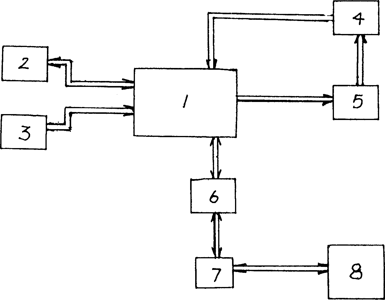
[0011] Depend on figure 1 , in an embroidery machine with a USB interface circuit of the present invention, it mainly includes a control unit 1, a keyboard / display unit 2, a pattern input unit 3, a mechanical execution unit 4 and a detection unit 5, and another one is connected with the control circuit USB interface circuit 6 and a USB connector 7, the USB connector is connected with the USB connector of PC 8. Among them, the control unit 1 is composed of a CPU microprocessor circuit, a SRAM storage circuit, and a CPLD programmable logic circuit. The mechanical execution unit 4 mainly includes a stepping motor driving circuit in the X direction, a stepping motor driving circuit in the Y direction, and a motor control circuit in the Z direction. , the detection unit 5 mainly includes a broken thread detection circuit, a rewinding position circuit, a presser foo...


PUM


Abstract

The invention relates to an embroidering machine that carries USB interface. It includes keyboard / display unit, design input unit, mechanism executing unit, detecting unit, USB interface circuit connecting to the control circuit and a USB plunger. The USB plunger connects to PC and the embroidering machine can realize the information exchange with PC. PC extends the function of the embroidering machine.

Description

technical field [0001] The invention relates to an embroidery machine, in particular to an automatic embroidery machine controlled by a microprocessor. Background technique [0002] A general embroidery machine has an embroidery frame for setting embroidery workpieces. By controlling the movement of the embroidery frame in the X-axis and Y-axis directions and cooperating with the movement of the sewing needle mechanism to form pattern stitches, the embroidery of various predetermined patterns can be completed. . Existing automatic embroidery machines have been improved from general program control to single-chip microprocessor control. Usually a household embroidery machine is provided with only one head, while an industrial embroidery machine can have dozens of heads, and each head is equipped with a variety of different color threads. The embroidery frame for fixed work is generally made of Two stepping motors in the X direction and Y direction are driven to form various...

Claims


Application Information

Patent Timeline
Patent Type & Authority Applications(China)
IPC IPC(8): D05C5/04
Inventor 罗万春黄坚周昌达吴朝晖
Owner 上海上工佳源机电科技有限公司
Learn More