
Apparatus at a spinning room machine for drawing a clothing onto a roller

A spinning machine and equipment technology, applied in textiles and papermaking, deburring devices, fiber processing, etc., can solve the problems that the rotation speed cannot be kept constant, the equipment is complicated, and cannot be adjusted.

Inactive Publication Date: 2011-08-03
TRUTZSCHLER GMBH & CO KG
View PDF0 Cites 0 Cited by
  • Summary
  • Abstract
  • Description
  • Claims
  • Application Information

AI Technical Summary

Problems solved by technology

In this known device, the disadvantage is that the predetermined rotation speed cannot be kept constant when the load changes
Inability to automatically adjust the actual value of the rotational speed to a predetermined rotational speed
In addition, this known device is also very complex

Method used


Image

  • Apparatus at a spinning room machine for drawing a clothing onto a roller
  • Apparatus at a spinning room machine for drawing a clothing onto a roller
  • Apparatus at a spinning room machine for drawing a clothing onto a roller

Examples


Embodiment Construction

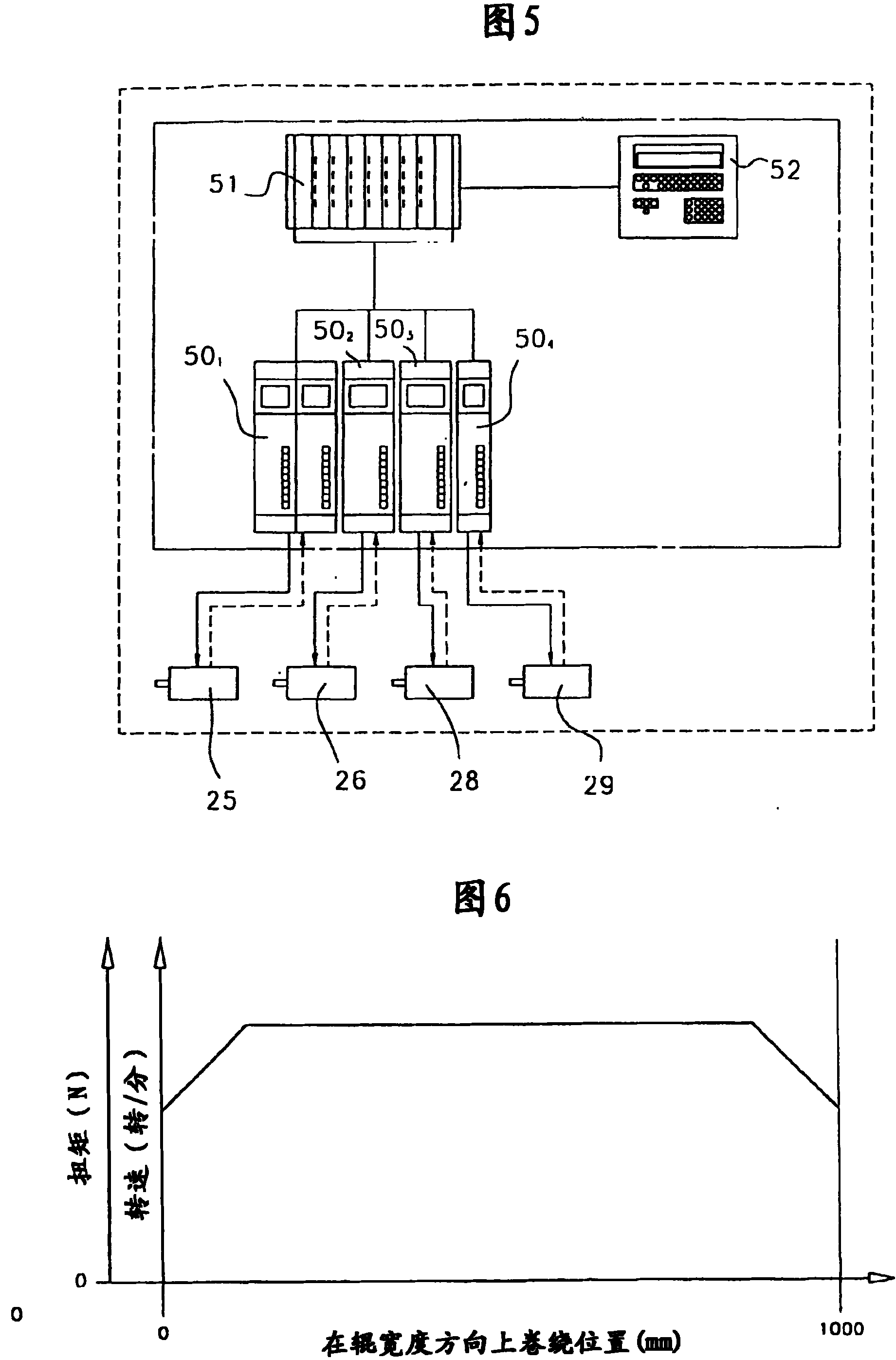
[0019] figure 1 Shown is a card K, for example, a card of Trützschler TC 03 type, which has a feed roll 1, feed table 2, licker-in rolls 3a, 3b, 3c, cylinder 4, doffer 5, stripping roll 6 , gripping rollers (nip rollers) 7,8, fiber web guiding element 10, take-off roller 11,12, have carding flat deflection roller 13a, 13b and the rotary carding flat 13 of carding flat bone 14 (card tip bars) , can 15, and coiler 16. The curved arrows show the direction of rotation of the individual rollers. Reference numeral M shows the center (axis) of the cylinder 4 . Reference numeral 4a shows the covering cloth, and reference numeral 4b shows the rotation direction of the cylinder 4 . Reference sign C shows the direction of rotation of the revolving card flat 13 at the carding position, and reference sign B shows the direction of movement of the card flat bone 14 on the reverse side. Reference numeral 17 shows a cleaning roller for the stripping roller 6 and reference numeral 18 design...


PUM


Abstract

In an apparatus at a spinning room machine, especially a carding machine, cleaner or the like, for drawing a clothing onto a roller using a roller drive unit, which apparatus comprises a drive motor arranged to be in drive connection with the roller drive unit or with at least one roller of the machine, the drive motor co-operates with a rotary speed adjustment device. In order to allow, by simple means, automatic matching of the actual value of the speed of rotation to a prespecified value of the speed of rotation, the drive motor co-operates with a closed-loop rotary speed control device which is incorporated into the control and regulation device of the spinning room machine.

Description

technical field [0001] The present invention relates to a device for winding a wrapping on a roller driven by a roller drive unit on a spinning machine, in particular a carding machine, a cleaner or the like, the device having a drive motor, It is arranged in driving connection with the roller drive unit or with at least one roller of the spinning machine, in which device the drive motor cooperates with a rotational speed regulating device. Background technique [0002] In the field of the textile industry, especially in the field of cards, there are a large number of rolls which must be provided with wrappings. Typically, these wraps are wound onto said rolls as the machine is being built. That is to say, the wrapping cloth is wound on these rollers in a state where they are not installed yet. However, the wrapping cloth is a wearable part, which must be replaced after a certain working time in daily use. This replacement is usually carried out at the user's site, with t...

Claims


Application Information

Patent Timeline
Patent Type & Authority Patents(China)
IPC IPC(8): D01G15/36D01G15/14D01G15/92
CPCD01G15/92
Inventor F·赫泽尔A·莱德
Owner TRUTZSCHLER GMBH & CO KG
Learn More