
Ring traveler and method for production the same

A production method and traveler technology, applied in the direction of textiles and papermaking, can solve the problems of high cost and impact, and achieve the effects of low cost, pollution avoidance and good sliding performance

Inactive Publication Date: 2006-04-19
BRACKER AG
View PDF2 Cites 0 Cited by
  • Summary
  • Abstract
  • Description
  • Claims
  • Application Information

AI Technical Summary

Problems solved by technology

However, relatively high costs in terms of production have a negative impact on cost

Method used


Image

  • Ring traveler and method for production the same
  • Ring traveler and method for production the same
  • Ring traveler and method for production the same

Examples


Embodiment Construction

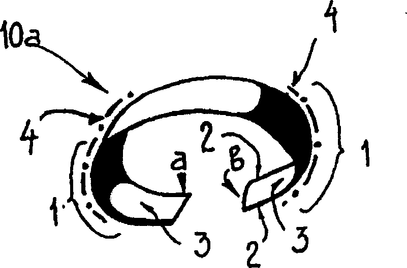
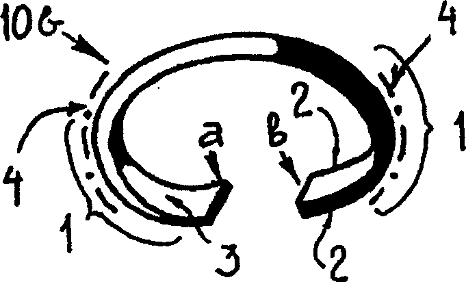
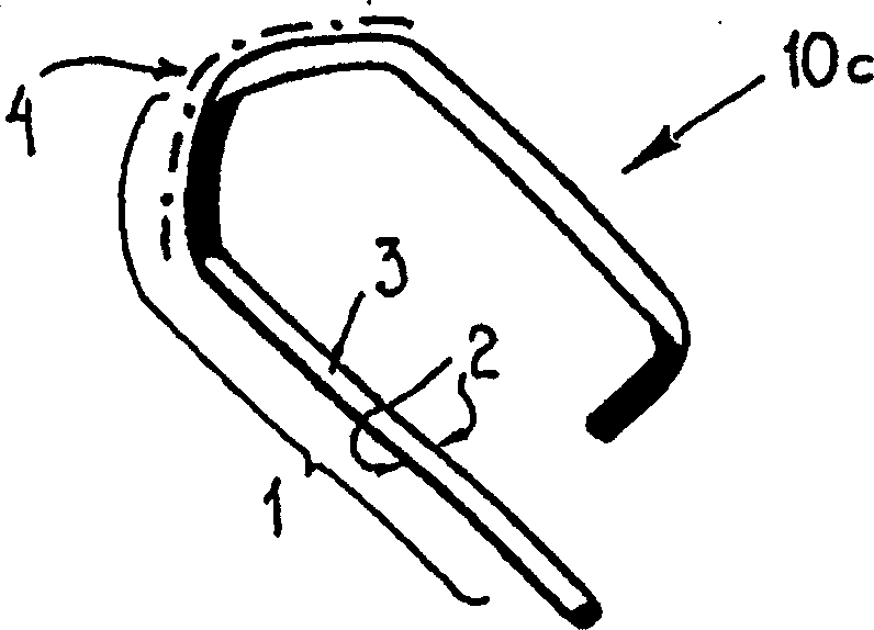
[0025] Figures 1a to 1f Shown are the travelers 10a to 10f in the various embodiments already described in International Patent WO 99 / 49113. Figure 1a and 1b C-shaped travelers 10a, 10b are shown, such as those normally used on the rings of the T-flanges of ring spinning machines or ring twisting machines. on the contrary, Figures 1c to 1f Ear and hook travelers 10c to 10f are shown. Travelers 10c and 10d are used on inclined flange rings, traveler 10e is used on conically running flange rings and traveler 10f is used on vertically running flange rings.

[0026] Those regions in which the travellers 10a to 10f slide in operation to form running surfaces on the flange rings are indicated with 1 in each case. In the case of C-shaped travelers 10a, 10b, both sides a, b are used as running surfaces due to their symmetrical construction. In the case of ear or hook travelers 10c to 10f, the running surface area 1 is clearly determined by the shape.

[0027] The traveler 10 ...


PUM

PropertyMeasurementUnit
Thicknessaaaaaaaaaa
Thicknessaaaaaaaaaa
Thicknessaaaaaaaaaa

Abstract

The invention relates to a ring traveler (10) comprising an uncoated core (20) that consists of an iron material. Said core is provided with an optionally composite nitrated marginal layer (23; 24) at least in the area of the running surfaces (1) with which it slides on the ring of a ring spinning frame or ring twisting frame.

Description

technical field [0001] The present invention relates to a method for producing a traveler and a traveler for a ring spinning or ring twisting machine. Background technique [0002] The traveler of the ring spinning and ring twisting machine moves at a high rotational speed (30 m / s to 50 m / s) on the ring of the corresponding ring spinning or ring twisting machine. Both the contact surfaces between the traveler and the ring and the contact surfaces between the traveler and the wire are subject to high levels of wear. But in order to increase production, the traveler needs to be increased to a higher operating speed. By obtaining a longer service life, costs are also reduced. [0003] In recent years it has become possible to significantly improve the running and working properties of these travelers by coating them with suitable materials. However, it has not been possible to improve the wear resistance at the lead-through channel so far. [0004] US Patent No. 4,677,817 d...

Claims


Application Information

Patent Timeline
IPC IPC(8): D01H7/60
CPCD01H7/604D01H7/60
Inventor J·凯吉
Owner BRACKER AG
Learn More