
Cooling roller flow guide device for amorphous ribbon production

The invention relates to a technology of a flow guiding device and an amorphous belt, which is applied to the field of cooling roller flow guiding devices for the production of amorphous belts, and can solve the problems of reducing the flow resistance of cooling water, weakening the cooling effect of the cooling roll, and increasing the pressure difference between the inlet and outlet of the water channel. , to achieve the effect of reducing flow resistance, reducing pressure difference and improving cooling effect

Pending Publication Date: 2022-07-08
曼特(广东)材料有限公司
View PDF0 Cites 0 Cited by
  • Summary
  • Abstract
  • Description
  • Claims
  • Application Information

AI Technical Summary

Problems solved by technology

[0006] Aiming at the deficiencies of the prior art, the present invention provides a cooling roll deflector for the production of amorphous strips, which can greatly reduce the flow resistance of cooling water, reduce the mechanical energy dissipation and temperature rise caused by fluid viscosity, and reduce the water flow of the cooling roll. The pressure difference is also greatly reduced, which improves the cooling effect of the cooling roller, and solves the problem that the traditional waterway structure is in the annular space, and only the friction force of the side wall of the space drives the water flow to rotate, so the angular velocity of the water flow lags far behind The angular velocity of the radial hole causes the resistance of the water flow, which leads to an increase in the pressure difference between the inlet and outlet of the waterway, which not only increases energy consumption, but also causes attenuation of the cooling effect of the cooling roller.

Method used


Image

  • Cooling roller flow guide device for amorphous ribbon production
  • Cooling roller flow guide device for amorphous ribbon production
  • Cooling roller flow guide device for amorphous ribbon production

Examples


Embodiment Construction

[0025] The technical solutions in the embodiments of the present invention will be described clearly and completely below. Obviously, the described embodiments are only a part of the embodiments of the present invention, rather than all the embodiments. Based on the embodiments of the present invention, all other embodiments obtained by those of ordinary skill in the art without creative efforts shall fall within the protection scope of the present invention.

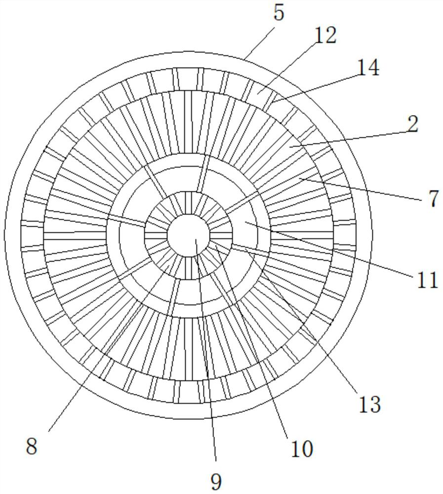
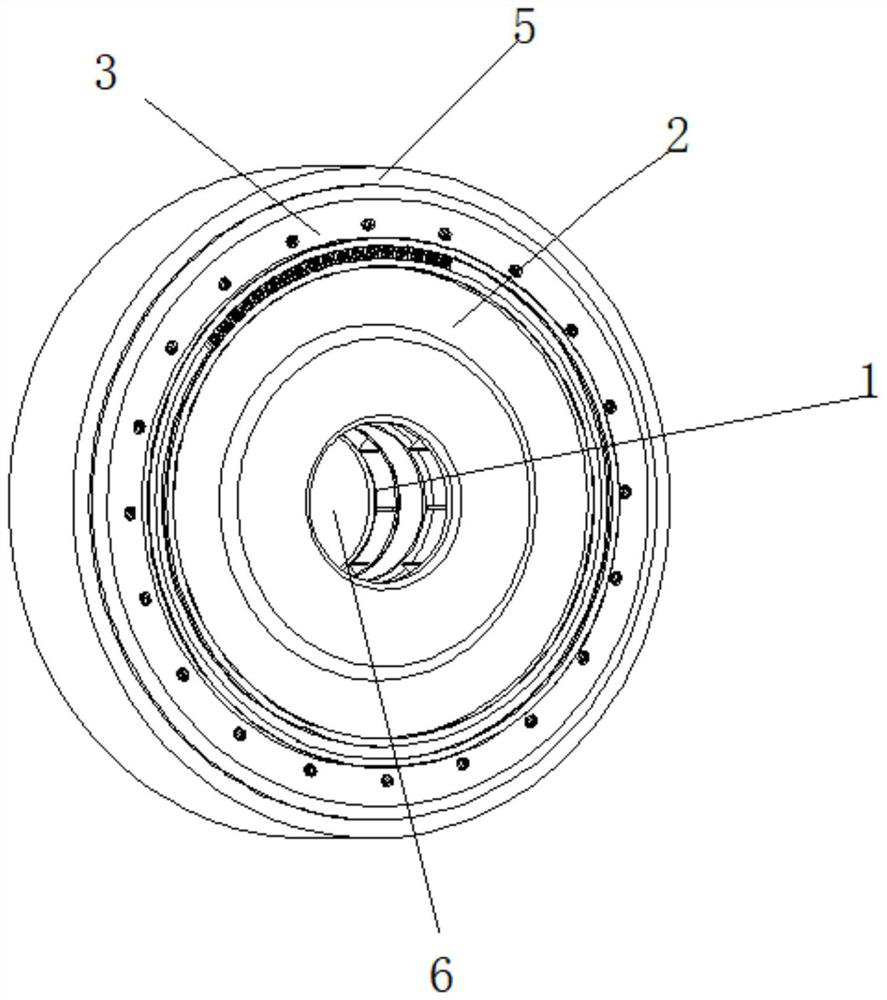
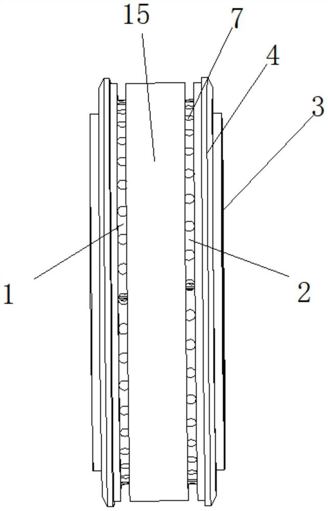
[0026] see Figure 1-4 , A cooling roll guide device for amorphous belt production, including a left support plate 1 and a right support plate 2, the opposite sides of the left support plate 1 and the right support plate 2 are fixedly connected with an end cover 3, and the outer side of the end cover 3 is fixedly connected A gland 4 is fixedly connected, a connection sleeve 15 is also fixedly connected at the connection between the left support plate 1 and the right support plate 2, a copper sleeve 5 is fixedly connecte...


PUM


Abstract

The invention relates to the technical field of amorphous ribbon production, and discloses a cooling roller flow guide device for amorphous ribbon production, the cooling roller flow guide device comprises a left supporting disc and a right supporting disc, the opposite sides of the left supporting disc and the right supporting disc are fixedly connected with end covers, the outer sides of the end covers are fixedly connected with glands, and the joint of the left supporting disc and the right supporting disc is further fixedly connected with a connecting sleeve; copper sleeves are fixedly connected to the outer sides of the left supporting disc and the right supporting disc, main shaft mounting holes are formed in the centers of the left supporting disc and the right supporting disc, a plurality of radial holes are formed in the left supporting disc and the right supporting disc, main shafts are fixedly connected to the interiors, corresponding to the main shaft mounting holes, of the left supporting disc and the right supporting disc, and main shaft center holes are formed in the main shafts. The cooling roller flow guide device for amorphous ribbon production has the advantages that the flow resistance of cooling water is greatly reduced, mechanical energy dissipation and temperature rise caused by fluid viscosity are reduced, the pressure difference of a cooling roller water path is also greatly reduced, and the cooling effect of the cooling roller is improved.

Description

technical field [0001] The invention relates to the technical field of amorphous strip production, in particular to a cooling roll guide device for amorphous strip production. Background technique [0002] The molten steel is rapidly cooled at a speed of millions of degrees per second. It only takes one thousandth of a second to reduce the molten steel of 1300 ° C to below 200 ° C. The cooling process is very fast, and the atoms are solidified before they can be rearranged. An alloy in which the atoms are arranged in a random state. An amorphous alloy is thus produced, forming an amorphous ribbon. [0003] In the production of amorphous ribbons, cooling rolls need to be used for high-speed cooling. At present, the cooling water circuit structure in the core of the cooling rolls is that the cooling water directly enters the central hole of the main shaft, and then comes out from the radial hole of the main shaft and enters the radial shape in the support plate. inside the h...

Claims


Application Information

Patent Timeline
IPC IPC(8): B22D11/06
CPCB22D11/0682
Inventor 涂崇韬皮宇昂
Owner 曼特(广东)材料有限公司
Learn More