
Lithium ion battery

A technology of lithium-ion batteries and lithium salts, which is applied in the manufacture of battery electrodes, secondary batteries, and electrolyte batteries, etc., and can solve problems such as internal resistance growth, serious lithium analysis, and poor long-term cycle performance of batteries

Pending Publication Date: 2022-06-03
SHENZHEN CAPCHEM TECH
View PDF0 Cites 1 Cited by
  • Summary
  • Abstract
  • Description
  • Claims
  • Application Information

AI Technical Summary

Problems solved by technology

[0006] The purpose of the present invention is to provide a lithium-ion battery which has the ability to cycle and store at high temperatures in order to overcome the problems of poor long-term cycle performance, increased internal resistance, and serious lithium analysis of high-pressure lithium-ion batteries in the prior art. The advantages of good performance, and can significantly improve the phenomenon of lithium precipitation after long-term cycling, and inhibit the growth of internal resistance

Method used


Image

  • Lithium ion battery
  • Lithium ion battery
  • Lithium ion battery

Examples


Embodiment 1

[0095] 1) Preparation of electrolyte

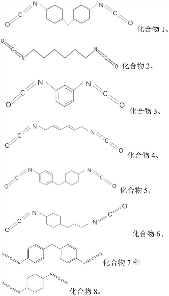
[0096] Ethylene carbonate (EC), diethyl carbonate (DEC), and ethyl methyl carbonate (EMC) were mixed in a mass ratio of EC:DEC:EMC=1:1:1, and then lithium hexafluorophosphate (LiPF) was added to the resulting mixture. 6 ) to a molar concentration of 1 mol / L, and then add compound 1 of 0.2% by weight of the total electrolyte mass (note: compound 1 here is compound 1 in the specification, the same below);

[0097] 2) Preparation of positive electrode sheet

[0098] The cathode active material LiCoO 2 (The surface has a metal oxide coating layer, LiCoO in the positive electrode active material 2 100%), conductive agent conductive carbon black Super-P and binder polyvinylidene fluoride (PVDF) were uniformly mixed in a weight ratio of 93:4:3, and then dispersed in N-methyl-2 - In pyrrolidone (NMP), the positive electrode slurry is obtained; the positive electrode slurry is uniformly coated on both sides of the aluminum foil, dried, rolled (...

Embodiment 2-22 and comparative example 1-5

[0107] Carry out according to the method of Example 1, the difference is that the positive electrode active material (with or without metal oxide coating layer) of the lithium ion battery, the compaction density of the positive and negative electrode materials, and the formula (1) added in the electrolyte The types and contents of the compounds, the types and contents of other additives, and the charge cut-off voltage are different, and the specific contents are shown in Table 1.

[0108] Table 1

[0109]

[0110] The relevant properties of the lithium ion batteries prepared in Examples 1-22 and Comparative Examples 1-5 are shown in Table 2.

[0111] Table 2

[0112]

[0113] From the results of Examples 1-3 and Comparative Examples 1-3, it can be seen that within the charge cut-off voltage range defined in the present invention, with the increase of the compaction density of the positive and negative electrodes, by adding the compound represented by the formula 1, it c...


PUM

PropertyMeasurementUnit
Specific surface areaaaaaaaaaaa
Compaction densityaaaaaaaaaa

Abstract

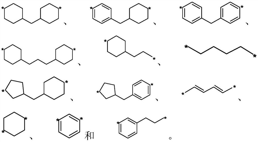
The present invention relates to the technical field of new energy, and discloses a lithium ion battery, the lithium ion battery comprises a positive electrode, a negative electrode, a separator arranged between the positive electrode and the negative electrode, and a non-aqueous electrolyte, the positive electrode contains a positive electrode material, and a positive electrode active material of the positive electrode material contains Li1-xCoO2 (0 < = xlt; a metal oxide coating layer is arranged on the surface of the Li1-xCoO2; the non-aqueous electrolyte comprises an organic solvent, a lithium salt and a compound represented by a formula (1), in the formula (1), R1 is one or more of chain-shaped, cyclic and aromatic groups with 2-20 carbon atoms, and the charging cut-off voltage of the lithium ion battery is 4.35 V or above. The lithium ion battery has the advantages of good circulation and storage performance at high temperature, and can significantly improve the lithium precipitation phenomenon after long-term circulation and inhibit the increase of internal resistance.

Description

technical field [0001] The invention relates to the technical field of new energy, in particular to a lithium ion battery. Background technique [0002] Lithium-ion batteries have been widely used in the field of 3C digital products such as mobile phones, notebook computers, and new energy vehicles because of their high operating voltage, wide operating temperature range, high energy density and power density, no memory effect and long cycle life. application. In recent years, with the continuous development of thin and light 3C digital products, the requirements for the energy density of lithium-ion batteries are getting higher and higher. Therefore, it is urgent to improve the energy density of lithium-ion batteries. [0003] At present, there are two main methods to improve the energy density of batteries. One is to increase the charge cut-off voltage of the positive electrode, and the other is to pressurize the active material layer of the electrode to achieve high den...

Claims


Application Information

Patent Timeline
IPC IPC(8): H01M10/0525H01M10/0566H01M10/0567H01M10/058H01M10/42H01M4/36H01M4/48H01M4/485H01M4/525
CPCH01M10/0525H01M10/058H01M4/485H01M4/525H01M4/366H01M4/48H01M10/4235H01M10/0566H01M10/0567Y02E60/10Y02P70/50
Inventor 钱韫娴胡时光王勇刘中波
Owner SHENZHEN CAPCHEM TECH
Learn More