
Upward medium-length hole non-coupling charging structure and application method

An application method and charging technology, applied in the field of mining, can solve the problems of limited bending performance of bamboo strips, affecting other operations in the mine, and low working efficiency of workers, achieving less preparation time for charging, shortening preparation time for charging, and reducing The effect of wasting blasting energy

Active Publication Date: 2022-05-24
CHINA MINMETALS CHANGSHA MINING RES INST
View PDF7 Cites 0 Cited by
  • Summary
  • Abstract
  • Description
  • Claims
  • Application Information

AI Technical Summary

Problems solved by technology

[0004] The above method has the following problems when it is implemented on the spot: first, strip explosives and bamboo strips can only be bound at the blasting site, and the binding takes a long time, so that it cannot be used in mines. The charging work is completed before the specified blasting time, which affects other operations in the mine; second, the bending performance of the bamboo strips is limited, and multiple bamboo strips must be tied to each other for relay, and the working conditions are poor when binding the bamboo strips at the hole, resulting in low work efficiency for workers; The third is that the integrity of the multiple bamboo strips tied head to tail is poor, and the loosening of the binding place during the process of pushing upwards into the blast hole will cause the bamboo strips to get stuck in the hole midway

Method used


Image

  • Upward medium-length hole non-coupling charging structure and application method

Examples


Embodiment 1

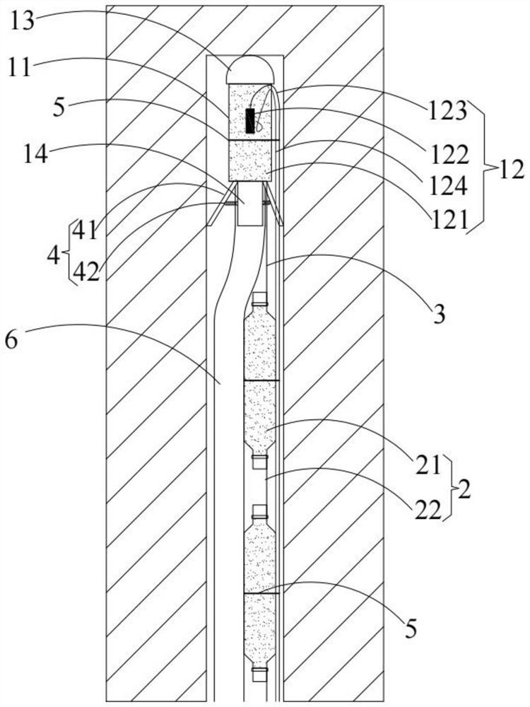
[0037] The present embodiment provides an application method of the uncoupled charge structure for the upward medium-deep hole, which includes the following steps:

[0038] S1. Use ropes to connect strip-shaped explosives 21 with a diameter of 50mm, a length of 200mm, and a string of end-to-end explosives 21 according to the required number of blast holes and a distance of 60mm, and tie them between the detonator shell 11 and the positioning socket 14;

[0039] S2, set the detonator 122 inside the detonating charge column 121, and put it into the detonator shell 11 together, the detonating tube 123 is connected to the detonator 122, one end of the detonating cord 124 is inside the detonating charge column 121, and the other end is connected to the detonating charge column 121 through the adhesive tape 5. All strip-shaped explosives 21 are fixed; at the same time, the detonating tube 123 and the detonating cord 124 are fixed to the outside of the detonator shell 11 with tape 5, ...


PUM


Abstract

The invention provides an upward medium-length hole non-coupling charging structure and an application method. The upward medium-length hole non-coupling charging structure comprises a detonating assembly, an explosive assembly and a first flexible connecting piece for connecting the detonating assembly with the explosive assembly. The explosive assembly comprises a plurality of explosives and a second flexible connecting piece for connecting the explosives end to end; the detonating assembly is provided with a triangular empennage used for fixing the charging structure in a blast hole. A charging pipe used for abutting against the detonating assembly is arranged at the bottom of the detonating assembly, and the charging structure can be pushed to the bottom of the blast hole during charging. When the explosive charging structure is applied, the second flexible connecting piece is adopted to connect the explosive into a whole end to end and bind the explosive to the tail end of the primer shell, the explosive charging pipe is arranged to abut against the positioning pipe base of the detonating assembly and send the positioning pipe base to the bottom of a hole, and after the explosive charging pipe is pulled out, the triangular empennage on the positioning pipe base is supported on the hole wall, so that the whole explosive charging structure is fixed in the blast hole; when the method is applied, the charging preparation time is short, the process is simple, the hole clamping probability is low, the operation efficiency is high, and the practical application value of popularization and utilization is achieved.

Description

technical field [0001] The invention relates to the technical field of mining, in particular to a non-coupling charging structure and an application method for an upward medium-deep hole. Background technique [0002] In the mining process, medium and deep hole blasting has been popularized due to its advantages of large production capacity, low mining cost and high degree of mechanization. In order to ensure that the retained rock mass is shaped according to the designed contour surface and prevent the damage of the surrounding rock, controlled blasting technologies such as smooth blasting and pre-split blasting are gradually applied to medium and deep hole blasting to keep the stope contour regular after blasting. In traditional blasting, the continuous columnar charge has disadvantages such as large unit consumption, high initial blasting pressure, and excessive rock crushing. to blasting vibration hazards and many other problems. [0003] At present, one of the key pro...

Claims


Application Information

Patent Timeline
Patent Type & Authority Applications(China)
IPC IPC(8): F42D1/08F42D3/04
CPCF42D1/08F42D3/04Y02E30/30
Inventor 张为星刘东锐李向东朱青凌张海云王亚军
Owner CHINA MINMETALS CHANGSHA MINING RES INST
Learn More