Device for additionally installing rubber sleeve on flange accessory
A technology of flange fittings and rubber sleeves, applied in metal processing, metal processing equipment, manufacturing tools, etc., can solve the problems of wasting human resources and time-consuming rubber sleeves
- Summary
- Abstract
- Description
- Claims
- Application Information
AI Technical Summary
Problems solved by technology
Method used
Image
Examples
Embodiment 1
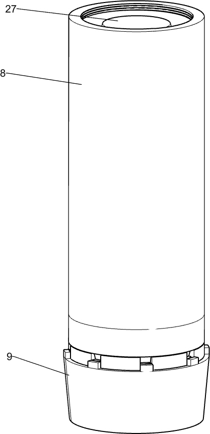
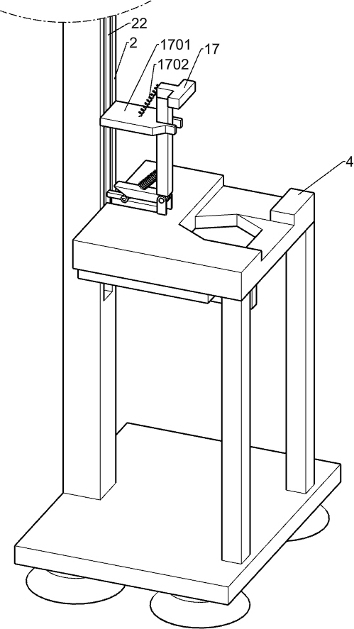
[0031] Such as figure 1 , figure 2 , image 3 , Figure 4 , Figure 5 , Image 6 , Figure 7 , Figure 12 and Figure 13As shown, a flange accessory is equipped with a rubber sleeve, including a base 1, a large bracket 2, a small bracket 3, a machined stage 4, a carrier 401, a hanging plate 5, an electric push rod 501, a sheet device, a mat Apparatus and push-up apparatus, wherein the upper pad device includes a coupling cover 6, a first outer casing 7, a second outer casing 8, a rotation table 9, a guide block 901, a rotating strut 902, a rotating disk 903, a rotary block 904, a rotating shell 10 The large gear 1001 and the pinion 1002, the rear side of the base 1 is fixed to the large bracket 2, and the large bracket 2 is connected to the upper side, and two small brackets 3 are fixed to the front side of the base 1, and the two small brackets 3 are common Following the processing table 4, the rear end of the processing table 4 is fixed to the large bracket 2, and there is a three-dime...
Embodiment 2
[0034] On the basis of Example 1, such as figure 1 and Figure 12 As shown, the upper device includes a first rail 20, an adapter block 21, a sliding bar 22, and a push rod 23, and a first rail 20 are opened on the large bracket 2, and the rear side of the adapter cover 6 is attached to the bond block 21, and the connection is connected. The block 21 is fixed with the slider 22, the slider 22 is an L-shaped, so that when the adapter cover 6 is moved downward, the slider 21 is moved downward, and the slider 22 is located in the first rail 20 and Sliding with the first rail 20, the sliding rod 22 secures two push rods 23, the push rod 23 is T-shaped, and the push rod 23 can move the carrier 401 upward movement.
[0035] When the electric push rod 501 pushes the adapter cover 6, the adapter cover 6 is moved downward, so that the slider 22 is moved downward, so that the push rod 23 is moved downward, so that the rod 23 is carrying When the disk 401 moves downward, when the carrier 401 ...
Embodiment 3
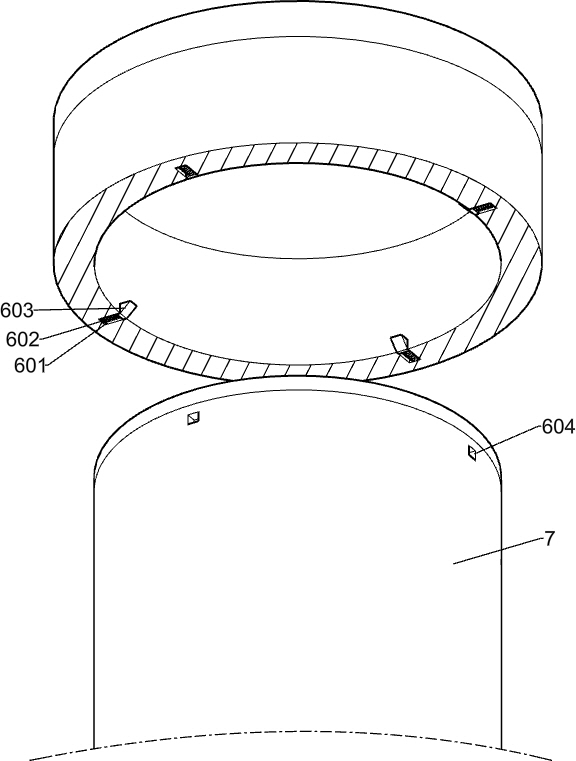
[0037] On the basis of Example 2, such as figure 2 As shown, the adapter includes a connecting spring 602 and a bonded slider 603, and there is 4 slide grooves 601 on the upper annular array of the adapter cover 6, and the sliding groove 601 is attached, and the sliding groove 601 is slidable. The adapter slider 603, the shape of the adapter slider 603 is a right angle trapezoid, and the upper bottom area of the adapter slider 603 is larger than the lower surface area, the inclined surface of the adapter slider 603 toward the outer side of the slide groove 601, and the adapter slider 603 does not slide from sliding Slide the groove 601, the adapter spring 602 is compressed when the adapter slider 603 slides in the sliding groove 601, and the first outer ring array of the first outer casing 7 has four adapter grooves 604, and the head of the sliding block can be attached. In the slot 604, when the head of the slider is engaged into the tank 604, the first outer casing 7 is attach...
PUM
 Abstract
Description
Claims
Application Information
 - R&D Engineer
- R&D Manager
- IP Professional
- Industry Leading Data Capabilities
- Powerful AI technology
- Patent DNA Extraction
Browse by: Latest US Patents, China's latest patents, Technical Efficacy Thesaurus, Application Domain, Technology Topic, Popular Technical Reports.
© 2024 PatSnap. All rights reserved.Legal|Privacy policy|Modern Slavery Act Transparency Statement|Sitemap|About US| Contact US: help@patsnap.com


