
Transformer substation monitoring and telecontrol system

A substation monitoring and monitoring system technology, applied in information technology support systems, electrical components, circuit devices, etc., can solve problems such as affecting the quality of point-to-point debugging, tight construction periods, and lack of systems.

Pending Publication Date: 2022-02-25
STATE GRID HEBEI ELECTRIC POWER CO LTD
View PDF0 Cites 0 Cited by
  • Summary
  • Abstract
  • Description
  • Claims
  • Application Information

AI Technical Summary

Problems solved by technology

According to the survey, the point-to-point workload of the substation accounts for about 30% of the overall commissioning work, and the point-to-point of the main plant generally takes 3 to 6 weeks. The labor intensity of the operators is high and the commissioning efficiency is low.
In addition, the risk of information omission and information error caused by manual acceptance check makes it difficult to ensure the consistency and accuracy of monitoring system signals, which affects the quality of point-to-point debugging
[0004] At present, the joint commissioning of substation remote control information must be implemented after the communication channel of the main factory station is connected. At this time, it is often close to the commissioning time of the substation, and the construction period is very tight.
In addition, the current on-site commissioning results of substations are basically recorded manually. The acceptance personnel generally refer to the previous manual commissioning records and repeat the previous tests on site. The manual method is still the main method. There is no verification system to support the acceptance work. not tall
In addition, for some new equipment, although it has been tested in the laboratory environment, it is different from the site after all. For the sake of safety and reliability, it is necessary to debug and verify the new system and new equipment reinstalled on site, but there is no corresponding at this stage. system

Method used


Image

  • Transformer substation monitoring and telecontrol system

Examples


Embodiment Construction

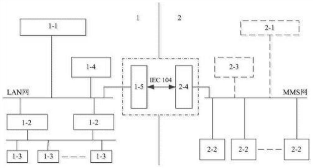
[0020] The following is attached figure 1 The principles and features of the present invention are described, and the examples given are only used to explain the present invention, and are not used to limit the scope of the present invention. In the following paragraphs the invention is described more specifically by way of example with reference to the accompanying drawings. Advantages and features of the present invention will be apparent from the following description and claims. It should be noted that all the drawings are in a very simplified form and use imprecise scales, and are only used to facilitate and clearly assist the purpose of illustrating the embodiments of the present invention.

[0021] It should be noted that when a component is said to be "fixed" to another component, it can be directly on the other component or there can also be an intervening component. When a component is said to be "connected" to another component, it may be directly connected to the...


PUM


Abstract

The invention relates to a transformer substation monitoring and telecontrol system. The system comprises a converter station monitoring system and a transformer substation monitoring system; the converter station monitoring system comprises an AC / DC operator work station, a control host, a local data acquisition I / O interface device, a converter station monitoring system server and a converter station gateway machine, wherein the AC / DC operator work station, the control host, the converter station monitoring system server and the converter station gateway machine communicate with one another through a station LAN network, the control host exchanges data with the local data acquisition I / O interface device through a field bus; front-end equipment carries out communication and data transmission with an existing substation auxiliary comprehensive monitoring system through a network, and stores videos and sounds of a first-aid repair site in the substation auxiliary comprehensive monitoring system; and an on-site video monitoring system arranged in a centralized monitoring center is connected with the substation auxiliary comprehensive monitoring system through a network.

Description

technical field [0001] The invention relates to the field of electrical engineering, in particular to a substation monitoring and telecontrol system. Background technique [0002] Substation monitoring is aimed at the use characteristics of users in the power industry. Combined with industrial control, security management and digital video, etc., using the existing network resources of the power grid, a multi-functional monitoring system integrating remote viewing system, access control system, fire protection system, environment and power monitoring system is designed. A networked comprehensive security management system integrating subsystems. In the on-site commissioning of substations, it is generally unnecessary to verify the functional problems of secondary devices such as logic and communication, but to focus on the verification of construction correctness, and use simulation to verify. The commissioning personnel apply electrical analog quantities and switches to the...

Claims


Application Information

Patent Timeline
IPC IPC(8): H02J13/00
CPCH02J13/00001H02J13/00002H02J13/00016H02J13/00032Y02B90/20Y04S40/124
Inventor 杨立波马斌袁龙李一鹏王亚军栗维勋
Owner STATE GRID HEBEI ELECTRIC POWER CO LTD
Learn More