
Workpiece rigidity testing method and application

A testing method and stiffness technology, applied in the direction of applying stable tension/pressure to test material strength, measuring devices, strength characteristics, etc., can solve the problem of long time for adjusting space angle and attitude, low test efficiency, and difficulty in obtaining large-scale Promote the application and other issues to achieve the effect of convenient installation and extensive promotion of application value

Pending Publication Date: 2021-12-03
武汉源威智能科技有限公司
View PDF0 Cites 0 Cited by
  • Summary
  • Abstract
  • Description
  • Claims
  • Application Information

AI Technical Summary

Problems solved by technology

[0003] In the existing technology, the joint robot is used for testing, and the normal direction of the test part is visually tested to test the stiffness. At this time, the object under test remains motionless, and the joint robot is used to adjust the spatial angle of the actuator; while the robot needs to be programmed to adjust the space. If the angle and posture take a long time, the test efficiency will be low, and it will be difficult to get a wide range of promotion and application

Method used


Image

  • Workpiece rigidity testing method and application
  • Workpiece rigidity testing method and application
  • Workpiece rigidity testing method and application

Examples


Embodiment Construction

[0036] The following will clearly and completely describe the technical solutions in the embodiments of the present invention with reference to the accompanying drawings in the embodiments of the present invention. Obviously, the described embodiments are only part of the embodiments of the present invention, not all of them. Based on the embodiments of the present invention, all other embodiments obtained by persons of ordinary skill in the art without creative efforts fall within the protection scope of the present invention.

[0037] It should be noted that all directional indications (such as up, down, left, right, front, back...) in the embodiments of the present invention are only used to explain the relationship between the components in a certain posture (as described in the accompanying drawings). Relative positional relationship, movement conditions, etc., if the specific posture changes, the directional indication will also change accordingly.

[0038] In addition, ...


PUM


Abstract

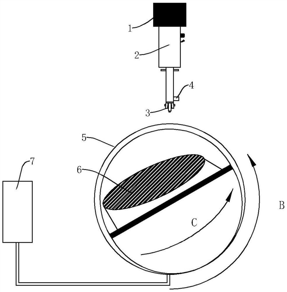
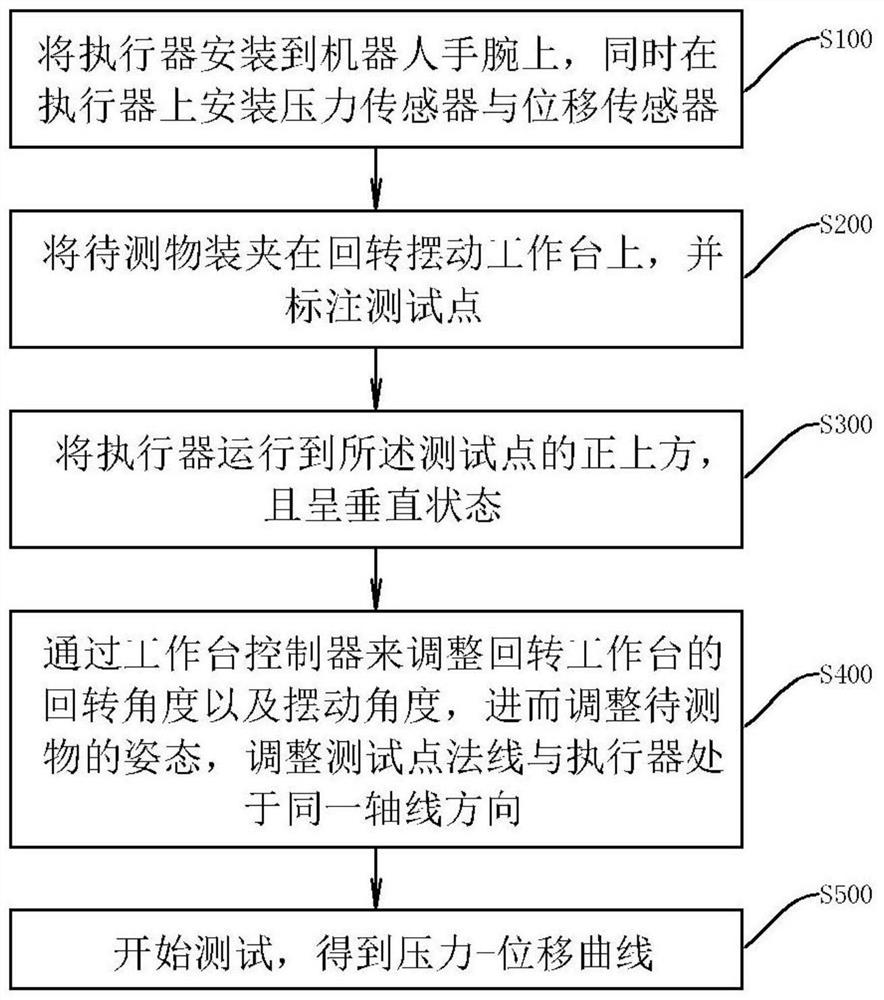
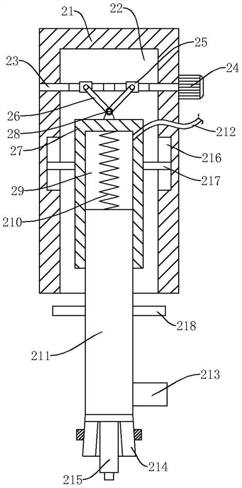
The invention relates to the technical field of rigidity testing, and particularly relates to a workpiece rigidity testing method. The method comprises the steps that an actuator is installed on a robot wrist, and meanwhile a pressure sensor and a displacement sensor are installed on the actuator; an object to be tested is clamped on the rotary swing workbench, and a test point is marked; an actuator is operated to the position right above the test point; the rotating angle and the swinging angle of the rotating and swinging workbench are adjusted through the workbench controller so that the posture of the object to be tested is adjusted, and the normal of the test point and the actuator are adjusted to be in the same axis direction; and testing is started, and a pressure-displacement curve is obtained. The beneficial effects of the invention are that adjustment of the spatial posture of the object to be tested can be realized through the rotating and swinging workbench, the posture of the object to be tested is adjusted through the robot wrist, the speed is low, rapid adjustment of the spatial postureof the object to be tested can be realized through the rotating and swing workbench in the embodiment, the use is faster and more convenient, and wide popularization and application values are realized.

Description

technical field [0001] The invention relates to the technical field of stiffness testing, in particular to a testing method and application of workpiece stiffness. Background technique [0002] Stiffness test is the process of determining the stiffness of an object, the process of determining the stiffness of an object, and the load required to cause the object to produce unit deformation is the stiffness. The stiffness of an object is related to its material properties, geometry, support, and the way loads act. [0003] In the existing technology, the joint robot is used for testing, and the normal direction of the test part is visually tested to test the stiffness. At this time, the object under test remains motionless, and the joint robot is used to adjust the spatial angle of the actuator; while the robot needs to be programmed to adjust the space. If the angle and posture take a long time, the test efficiency is low, and it is difficult to obtain a wide range of popula...

Claims


Application Information

Patent Timeline
Patent Type & Authority Applications(China)
IPC IPC(8): G01N3/08G01N3/02G01N3/04
CPCG01N3/08G01N3/02G01N3/04G01N2203/0019
Inventor 黄为吴峻峰
Owner 武汉源威智能科技有限公司
Learn More