
Connecting component of pull rod and cross beam, pull rod and cross beam assembly and construction method of pull rod and cross beam assembly

A technology for connecting components and connecting components, applied in the direction of building structure, construction, etc., can solve the problems of poor mechanical performance of building structures, affecting the aesthetics of building structures, occupying space for building structures, etc., to achieve simple connection operations and ensure spaciousness. and aesthetics, the effect of improving stress performance

Pending Publication Date: 2021-12-03
CCDI INT SHENZHEN DESIGN CONSULTANTS
View PDF0 Cites 0 Cited by
  • Summary
  • Abstract
  • Description
  • Claims
  • Application Information

AI Technical Summary

Problems solved by technology

[0005] The object of the present invention is to provide a connecting member of a tie rod and a cross beam, a tie rod and a cross beam assembly and a construction method thereof, which are used to solve the problem in the prior art that the adjacent tie rods transmit loads through the cross beam and the stiffened plate resulting in poor mechanical performance of the building structure At the same time, it can avoid the connecting components from occupying the use space in the building structure and affecting the beauty of the building structure

Method used


Image

  • Connecting component of pull rod and cross beam, pull rod and cross beam assembly and construction method of pull rod and cross beam assembly
  • Connecting component of pull rod and cross beam, pull rod and cross beam assembly and construction method of pull rod and cross beam assembly
  • Connecting component of pull rod and cross beam, pull rod and cross beam assembly and construction method of pull rod and cross beam assembly

Examples


Embodiment Construction

[0038] The following will clearly and completely describe the technical solutions in the embodiments of the present invention with reference to the accompanying drawings in the embodiments of the present invention. Obviously, the described embodiments are only some, not all, embodiments of the present invention. Based on the embodiments of the present invention, all other embodiments obtained by persons of ordinary skill in the art without making creative efforts belong to the protection scope of the present invention.

[0039] In describing the present invention, it is to be understood that the terms "center", "upper", "lower", "front", "rear", "left", "right", "vertical", "horizontal", The orientations or positional relationships indicated by "top", "bottom", "inner", "outer", etc. are based on the orientations or positional relationships shown in the drawings, and are only for the convenience of describing the present invention and simplifying the description, rather than in...


PUM


Abstract

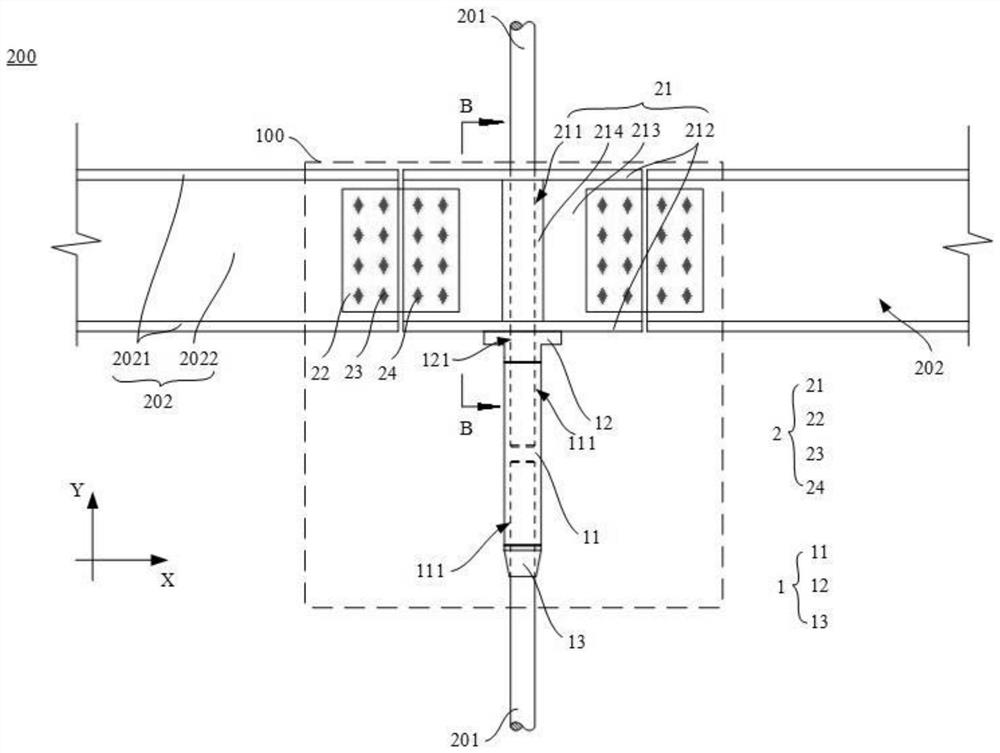
The invention discloses a connecting component of a pull rod and a cross beam, a pull rod and cross beam assembly and a construction method of the pull rod and cross beam assembly, relates to the field of building structures, and aims at solving the problem that the stress performance of a building structure is poor in the prior art as adjacent pull rods transmit loads through a cross beam and a stiffening plate. The connecting component is used for connecting two pull rods and two cross beams and comprises a first connecting piece, wherein one end of the first connecting piece is connected with one pull rod and the other end thereof is connected with the other pull rod; and a second connecting piece, wherein a first through hole for the pull rod to penetrate through is formed in the second connecting piece, and the second connecting piece is further used for being connected with the two cross beams; when the two pull rods and the two cross beams are connected with the connecting component, the end, connected with one pull rod penetrating through the first through hole, of the first connecting piece directly or indirectly abuts against the second connecting piece. According to the connecting component provided by the invention, the two pull rods directly transmit a force through the first connecting piece, the force transmission is relatively clear, and the stress performance of a building structure using the connecting component is improved.

Description

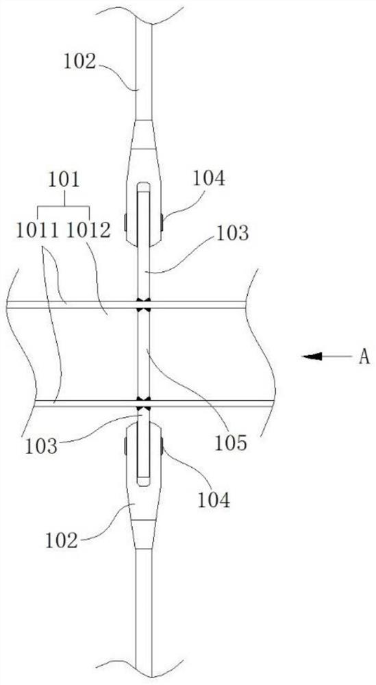
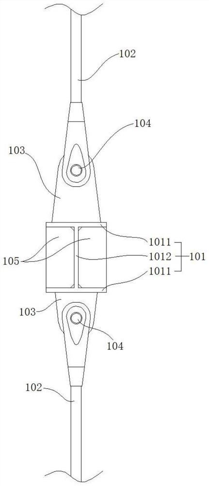
technical field [0001] The invention relates to the field of building structures, in particular to a connecting member of a tie rod and a beam, an assembly of the tie rod and the beam and a construction method thereof. Background technique [0002] Due to its advantages of high strength and small cross-section, steel tie rods are increasingly used as rods bearing gravity loads. When steel tie rods are vertically arranged as rods bearing gravity loads, vertically adjacent steel rods The tie rods need to be connected to the transverse steel beams at the steel beams. [0003] see figure 1 and figure 2 , in the related art, the lug plate 103 is welded on the upper and lower surfaces of the steel beam 101, and the steel tie rod 102 is connected to the lug plate 103 through the pin shaft 104, so that the connection between the steel beam 101 and the steel tie rod 102 is realized. [0004] In practical application, the steel beam 101 is generally I-shaped steel, including two f...

Claims


Application Information

Patent Timeline
Patent Type & Authority Applications(China)
IPC IPC(8): E04B1/24E04B1/58
CPCE04B1/24E04B1/2403E04B1/5812E04B2001/2415E04B2001/2427E04B2001/2418E04B2001/2457E04B2001/2448
Inventor 刘云浪傅学怡吴国勤吴兵周坚荣冯叶文
Owner CCDI INT SHENZHEN DESIGN CONSULTANTS
Learn More