
Multi-functional overflow groove assembly for steel belt cooling machine

A steel strip cooling and overflow tank technology, applied in the direction of coating, etc., can solve the problems of not being able to obtain multiple strip products at the same time, increase the difficulty of maintenance, and cannot change the width, so as to achieve convenient replacement, improve production efficiency, The effect of increasing utilization

Pending Publication Date: 2020-12-29
ZHANGJIAGANG RAIDSANT MACHINERY
View PDF0 Cites 0 Cited by
  • Summary
  • Abstract
  • Description
  • Claims
  • Application Information

AI Technical Summary

Problems solved by technology

The fluid has good fluidity at high temperature and can be pumped into the overflow tank. However, at the end of production, the residual fluid in the overflow tank is difficult to quickly clean up. After cooling, it is fixed in the overflow tank, which increases the difficulty of maintenance.
[0004] In addition, most of the products obtained through the overflow tank are in the form of flakes, and the width cannot be changed, and it is impossible to obtain multiple strip-shaped products at the same time. The structure of the product is relatively simple and needs to be improved.

Method used


Image

  • Multi-functional overflow groove assembly for steel belt cooling machine
  • Multi-functional overflow groove assembly for steel belt cooling machine
  • Multi-functional overflow groove assembly for steel belt cooling machine

Examples


Embodiment 1

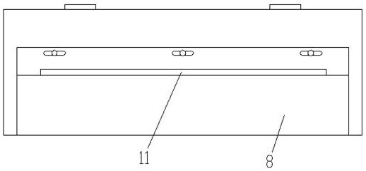
[0030] like image 3 As shown, when one guide hole 11 is used, the degree of coincidence (lateral misalignment) between the guide hole 11 and the overflow square hole 15 can be changed by laterally shifting the flow control plate 7, thereby changing the width of the sheet product;

Embodiment 2

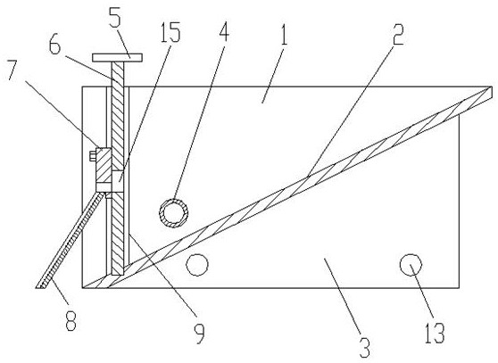
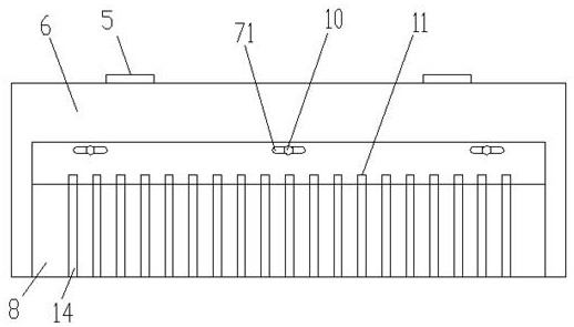
[0032] like figure 1 and 2 As shown, a plurality of guide holes 11 are used, so that multiple fluids are output synchronously, and when there are multiple guide holes 11, the top surface of the guide plate 8 is concavely provided with guide grooves corresponding to the guide holes 11 one-to-one. 14. A plurality of fluids are sent to the surface of the steel belt of the steel belt cooler through the diversion groove 14, and after cooling and solidification, a plurality of strip-shaped products are formed to improve the production efficiency.

[0033] In this embodiment, in order to ensure the fluidity of the fluid in the overflow tank, the overflow tank is provided with a hot oil pipeline 4 that penetrates through the two side shields 1 . The hot oil pipeline 4 is located above the bottom plate 2, and the hot oil Both ends of the pipeline 4 are connected with a heat transfer oil circulation pipeline to heat the fluid in the overflow tank.

[0034] To sum up, the multifunction...


PUM


Abstract

The invention discloses a multi-functional overflow groove assembly for a steel belt cooling machine. The multi-functional overflow groove assembly comprises an overflow groove body and a gate plate assembly, the overflow groove body comprises side protection plates and a bottom plate, the side protection plates are vertically arranged at the two ends of the bottom plate extending obliquely downwards, and guide rails extending downwards to the surface of the bottom plate are arranged on the inner walls of the side protection plates correspondingly; and the gate plate assembly comprises a gateplate, a flow control plate and a flow guide plate, the gate plate is arranged between the guide rails on the two sides, an overflow square hole extending transversely is formed in the gate plate, theflow control plate is arranged on the front face of the gate plate to cover the overflow square hole, and one or more flow guide holes communicating with the overflow square hole are formed in the flow control plate. Through the mode and according to the multi-functional overflow groove assembly for the steel belt cooling machine, the utilization rate of raw materials and the convenience of maintenance and cleaning are improved, the width of sheet-shaped products can be changed or multiple belt-shaped products can be produced at the same time, and the production efficiency is improved.

Description

technical field [0001] The invention relates to the field of mechanical equipment, in particular to a multifunctional overflow groove assembly for a steel belt cooler. Background technique [0002] The steel belt cooler is a kind of equipment for fluid cooling and solidification. It can distribute the fluid on the steel belt through the overflow groove, and obtain a sheet-like product after cooling and solidification. [0003] After the fluid is introduced into the overflow tank, the liquid level is raised. The upper fluid overflows to the steel belt through the front edge of the overflow tank. After the steel belt is transported and cooled, sheet-like products, such as asphalt boards, are obtained. . The fluid has good fluidity at high temperature and can be pumped into the overflow tank. However, at the end of production, the residual fluid in the overflow tank is difficult to quickly clean up. After cooling, it is fixed in the overflow tank, which increases the difficult...

Claims


Application Information

Patent Timeline
Patent Type & Authority Applications(China)
IPC IPC(8): B29C41/46B29C41/34
CPCB29C41/46B29C41/34
Inventor 褚忠平褚海峰褚云峰
Owner ZHANGJIAGANG RAIDSANT MACHINERY
Learn More