A Quick Glazing Equipment for Soup Spoons
A fast and soup spoon technology, applied in ceramic forming machines, manufacturing tools, etc., can solve the problem of uneven glaze on ceramic spoons
- Summary
- Abstract
- Description
- Claims
- Application Information
AI Technical Summary
Problems solved by technology
Method used
Image
Examples
Embodiment 1
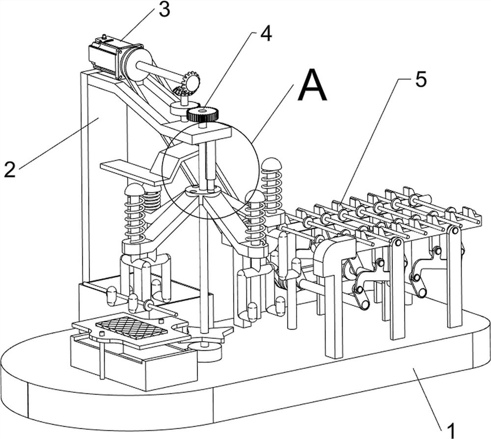
[0025] A quick glazing device for spoons, such as Figure 1-2 As shown, it includes a base plate 1, a mounting plate 2, a servo motor 3, a glazing mechanism 4 and a transmission mechanism 5. The mounting plate 2 is provided on the left rear side of the top of the base plate 1, the servo motor 3 is provided on the top of the mounting plate 2, and the top of the base plate 1 The left rear side is provided with a glazing mechanism 4, and the glazing mechanism 4 is connected with the output shaft of the servo motor 3;
[0026] When people need to glaze the spoon quickly, people first put the spoon on the spoon bar, then place the spoon bar on the parts of the transmission mechanism 5, and then start the servo motor 3, the output shaft of the servo motor 3 The rotation drives the parts of the transmission mechanism 5 to rotate, and the rotation of the parts of the transmission mechanism 5 drives the soup ladle to move to the left. Glazing the soup spoon, people can take off the gl...
Embodiment 2
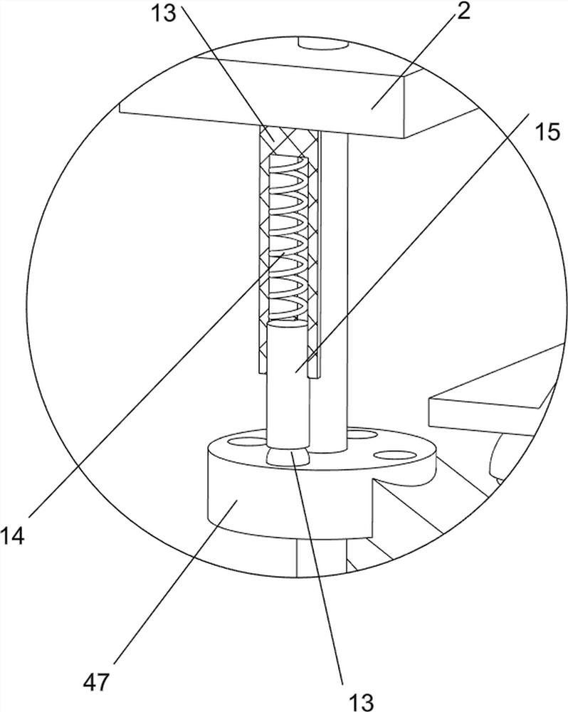
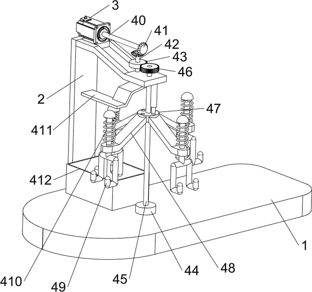
[0028] On the basis of Example 1, such as Figure 3-5 As shown, the glazing mechanism 4 includes a first rotating shaft 40, a bevel gear set 41, a second rotating shaft 42, a missing gear 43, a mounting seat 44, a third rotating shaft 45, all gears 46, a rotating disk 47, a swash plate 48, a hook rod 49. The first spring 410, the wedge-shaped plate 411 and the glazing pool 412. The output shaft of the servo motor 3 is provided with a first rotating shaft 40. The front side of the top of the mounting plate 2 is rotationally connected with a second rotating shaft 42. The middle part of the second rotating shaft 42 is There is a missing gear 43, a bevel gear set 41 is connected between the top of the second rotating shaft 42 and the front of the first rotating shaft 40, a mounting seat 44 is arranged in the middle of the top of the bottom plate 1, and a third rotating shaft 45 is connected to the top of the mounting seat 44 in a rotatable manner. The upper side of the third rotat...
Embodiment 3
[0033] On the basis of Example 2, such as Figure 6-7 Shown, also include four-corner turning block 6, water basin 7, movable plate 8, sponge pad 9, guide rod 10 and wedge block 11, the third rotating shaft 45 lower sides are provided with four-corner turning block 6, bottom plate 1 top left side is provided with There is a water basin 7, the left side of the top of the bottom plate 1 is evenly provided with guide rods 10, the number of guide rods 10 is 2, and movable plates 8 are slidably connected between the tops of the guide rods 10, and the middle part of the movable plate 8 is provided with a sponge pad 9. The bottom of the right side of the plate 8 is provided with a wedge-shaped block 11, and the wedge-shaped block 11 and the four-corner turning block 6 are extruded and fitted.
[0034] When people need to suck away the excess glaze water at the bottom of the spoon, people first add a certain amount of water in the water basin 7, so that the sponge pad 9 is in contact ...
PUM
 Abstract
Description
Claims
Application Information
 - R&D Engineer
- R&D Manager
- IP Professional
- Industry Leading Data Capabilities
- Powerful AI technology
- Patent DNA Extraction
Browse by: Latest US Patents, China's latest patents, Technical Efficacy Thesaurus, Application Domain, Technology Topic, Popular Technical Reports.
© 2024 PatSnap. All rights reserved.Legal|Privacy policy|Modern Slavery Act Transparency Statement|Sitemap|About US| Contact US: help@patsnap.com


