
Suspended ceiling for engineering construction

A technology for ceiling and engineering construction, applied in the direction of ceilings, building components, buildings, etc., can solve the problems of low structural installation stability, inconvenient installation and maintenance, ceiling surface corrosion, etc., to achieve structural installation stability and installation and maintenance. Enhancement, structural installation stability and the effect of improved installation and maintenance

Inactive Publication Date: 2020-06-19
鲁颖
View PDF9 Cites 1 Cited by
  • Summary
  • Abstract
  • Description
  • Claims
  • Application Information

AI Technical Summary

Problems solved by technology

[0004] The invention provides a ceiling for engineering construction, which can solve the problems of low structural installation stability, inconvenient installation and maintenance, and easy corrosion of the ceiling surface in the ceiling for engineering construction in the prior art

Method used


Image

  • Suspended ceiling for engineering construction
  • Suspended ceiling for engineering construction
  • Suspended ceiling for engineering construction

Examples


Embodiment 1

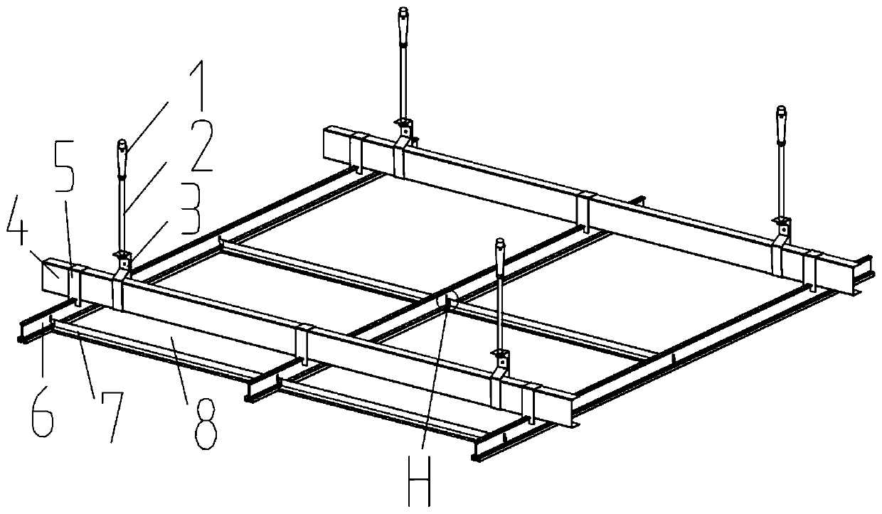
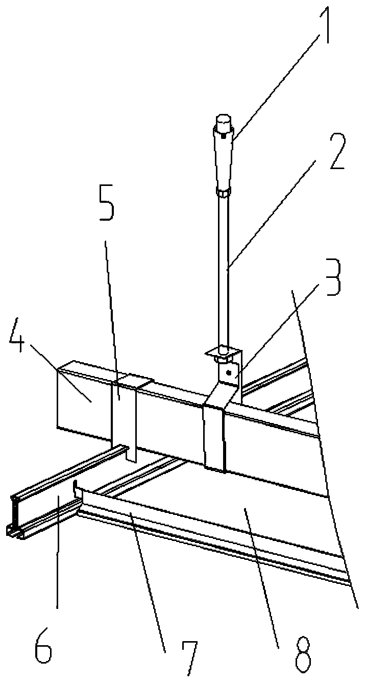
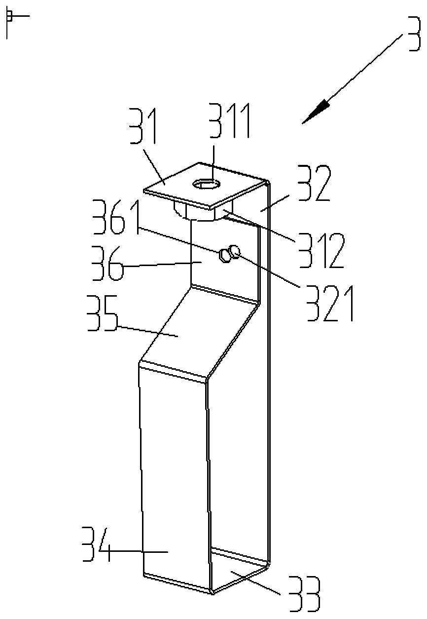
[0029] Such as Figure 1 to Figure 9 As shown, a ceiling for engineering construction provided by the embodiment of the present invention includes an expansion bolt 1, a suspender 2, a hanger 3 and a light steel keel 4, the expansion bolt 1 is sleeved on the upper end of the suspender 2, and the hanger 3 Threaded to the lower end of the suspender 2, it is characterized in that a pendant 5 is mounted on the light steel keel 4, the top of the pendant 5 is mounted on the upper end of the light steel keel 4, and the bottom of the pendant 5 is hoisted with a main frame 6, adjacent An auxiliary bone 7 is hung between two main bones 6 , and a ceiling 8 is installed between two adjacent main bones 6 and corresponding adjacent two auxiliary bones 7 .

[0030] Preferably, through the special structural support of the hanger 2, the hanger 5, the main bone 6 and the auxiliary bone 7, and the mutual cooperation between the ceiling system for the entire engineering construction, the structu...

Embodiment 2

[0050] Such as image 3 As shown, the welding nut 312 below the first wall 31 of the hanger 3 can be set as a pressure riveting nut. Although welding is superior to pressure riveting in terms of load-bearing strength, considering that the nut is arranged under the first wall 31, there is no falling off risk, so the welding nut 312 can be replaced with a pressure riveting nut, and the welding process is changed to a pressure riveting process, which avoids damage to the surface of the hanger 3 caused by welding.


PUM


Abstract

The invention discloses a suspended ceiling for engineering construction and belongs to the field of engineering construction. The suspended ceiling comprises expansion bolts, hanger rods, hangers andlight steel joists. The expansion bolts sleeve the upper ends of the hanger rods, and the hangers are in threaded connection with the lower ends of the hangers. The suspended ceiling is characterizedin that the hangers are hung on the light steel joists, the tops of the hangers are hung on the upper ends of the light steel joists, main keels are hoisted to the bottoms of the hangers, a sub keelis hung between every two adjacent main keels, and ceilings are installed between every two adjacent main keels and the corresponding two adjacent sub keels. Through supporting of a special structurewith the hangers, pendants, the main keels and the sub keels and cooperation of the overall suspended ceiling system for engineering construction, the structure mounting stability and installation andmaintenance of the overall system are improved, and the service life of the overall suspended ceiling system for engineering construction is prolonged.

Description

technical field [0001] The invention relates to the field of engineering construction, in particular to a ceiling for engineering construction. Background technique [0002] Ceilings for engineering construction are often seen in the field of engineering construction. Whether it is home decoration, office or other architectural decoration, it is used to beautify the space. Nowadays, with the improvement of the quality of life, in addition to the beautification effect and material requirements for ceilings for engineering construction, people also have higher requirements for the stability of the structural installation of ceiling systems for engineering construction. Common ceiling systems for engineering construction The connection between the keels is very loose, and the safety performance is low. For example, in large construction sites such as stations or airports, the height of the ceiling for engineering construction is also very high, and its stability directly affect...

Claims


Application Information

Patent Timeline
Patent Type & Authority Applications(China)
IPC IPC(8): E04B9/18E04B9/06E04B9/16E04B9/04E04B9/24
CPCE04B9/0435E04B9/06E04B9/16E04B9/18E04B9/24
Inventor 不公告发明人
Owner 鲁颖
Learn More