Device and method for improving force measurement accuracy of piezoelectric touch screen under step force
A technology of touch screen and step force, applied in the direction of electrical digital data processing, input/output process of data processing, instruments, etc., can solve problems such as unstable response relationship, achieve strong portability, improve force measurement accuracy, improve The effect of accuracy
- Summary
- Abstract
- Description
- Claims
- Application Information
AI Technical Summary
Problems solved by technology
Method used
Image
Examples
Embodiment 1
[0051] Embodiment 1 A device for improving the force measurement accuracy of a piezoelectric touch screen under step force
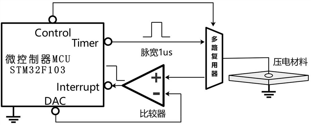
[0052] This embodiment includes a prestress detection circuit, a piezoelectric signal detection circuit and a signal acquisition unit.
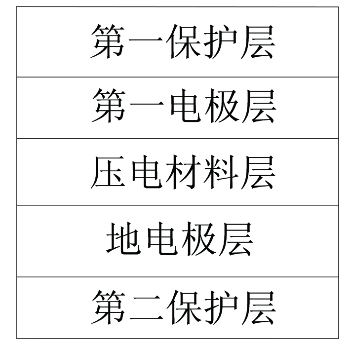
[0053] like figure 1As shown, the signal acquisition unit is implemented by a piezoelectric device, which includes a first protective layer, a first electrode layer, a piezoelectric material layer, a ground electrode layer and a second protective layer arranged in sequence from top to bottom. The first electrode layer and the second electrode layer are used as the output terminals of the signal acquisition unit. The charge generated by the forward piezoelectric effect is drawn out from the first electrode layer and the second electrode layer, and the ground electrode layer is grounded through the connected lead wire. Wherein, the first protective layer and the second protective layer are made of PET plastic, and the pi...
Embodiment 2
[0058] Embodiment 2 A method for improving the force measurement accuracy of a piezoelectric touch screen under step force
[0059] This embodiment adopts embodiment 1 to realize, such as Figure 5 As shown, follow the steps in the following order:
[0060] 1. Detection of prestress F static
[0061] S1. The control pin of the microcontroller sends a command to the multiplexer through the switch control pin of the multiplexer, and connects the timer output pin of the microcontroller with the piezoelectric material layer, and the microcontroller A 3.3V pulse signal with a length of 1us is generated by the timer and loaded on the piezoelectric material layer to charge the piezoelectric material layer to 3.3V;
[0062] S2. Once the time of 1us is up, the control pin of the microcontroller sends a command to the multiplexer through the switch control pin of the multiplexer, and the piezoelectric material layer is connected to the positive input terminal of the comparator. The ...
PUM
 Abstract
Description
Claims
Application Information
 - R&D Engineer
- R&D Manager
- IP Professional
- Industry Leading Data Capabilities
- Powerful AI technology
- Patent DNA Extraction
Browse by: Latest US Patents, China's latest patents, Technical Efficacy Thesaurus, Application Domain, Technology Topic, Popular Technical Reports.
© 2024 PatSnap. All rights reserved.Legal|Privacy policy|Modern Slavery Act Transparency Statement|Sitemap|About US| Contact US: help@patsnap.com


