
Heat transfer devices and methods for facilitating convective heat transfer with heat source or cold source

A heat transfer equipment, convective heat transfer technology, applied in auxiliary equipment, air handling equipment, indirect heat exchangers, etc., can solve the problems of coolant drive, difficult to cool heating equipment, etc.

Pending Publication Date: 2020-02-21
THE BOEING CO
View PDF0 Cites 0 Cited by
  • Summary
  • Abstract
  • Description
  • Claims
  • Application Information

AI Technical Summary

Problems solved by technology

However, with existing technology, it is difficult to cool heat-generating devices located at the perimeter of the item / body / structure due to the difficulty of driving the coolant to the perimeter

Method used


Image

  • Heat transfer devices and methods for facilitating convective heat transfer with heat source or cold source
  • Heat transfer devices and methods for facilitating convective heat transfer with heat source or cold source
  • Heat transfer devices and methods for facilitating convective heat transfer with heat source or cold source

Examples


Embodiment Construction

[0021] Apparatus and methods for enclosing and / or attaching to a heat source and facilitating convective, conductive, and / or radiative heat transfer from the heat source are disclosed. Generally, in the figures, elements that may be included in a given example are shown in solid lines, while elements that are optional for a given example are shown in dashed lines. However, elements shown in solid lines are not essential to all examples of the present disclosure, and elements shown in solid lines may be omitted from specific examples without departing from the scope of the present disclosure.

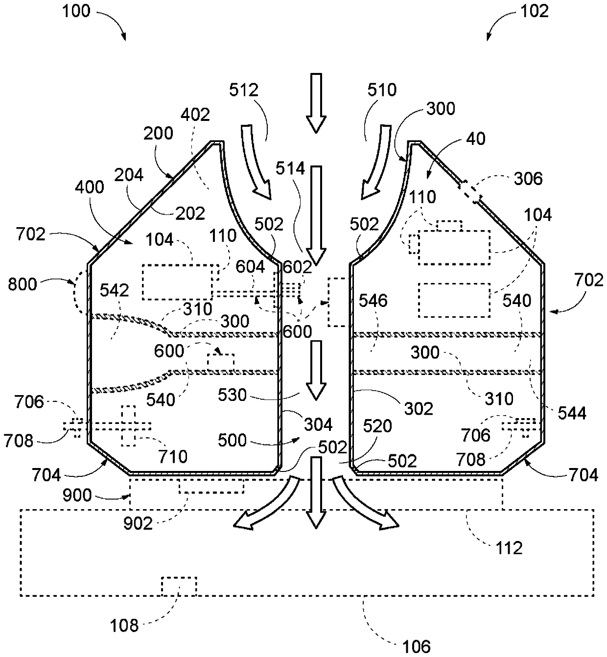
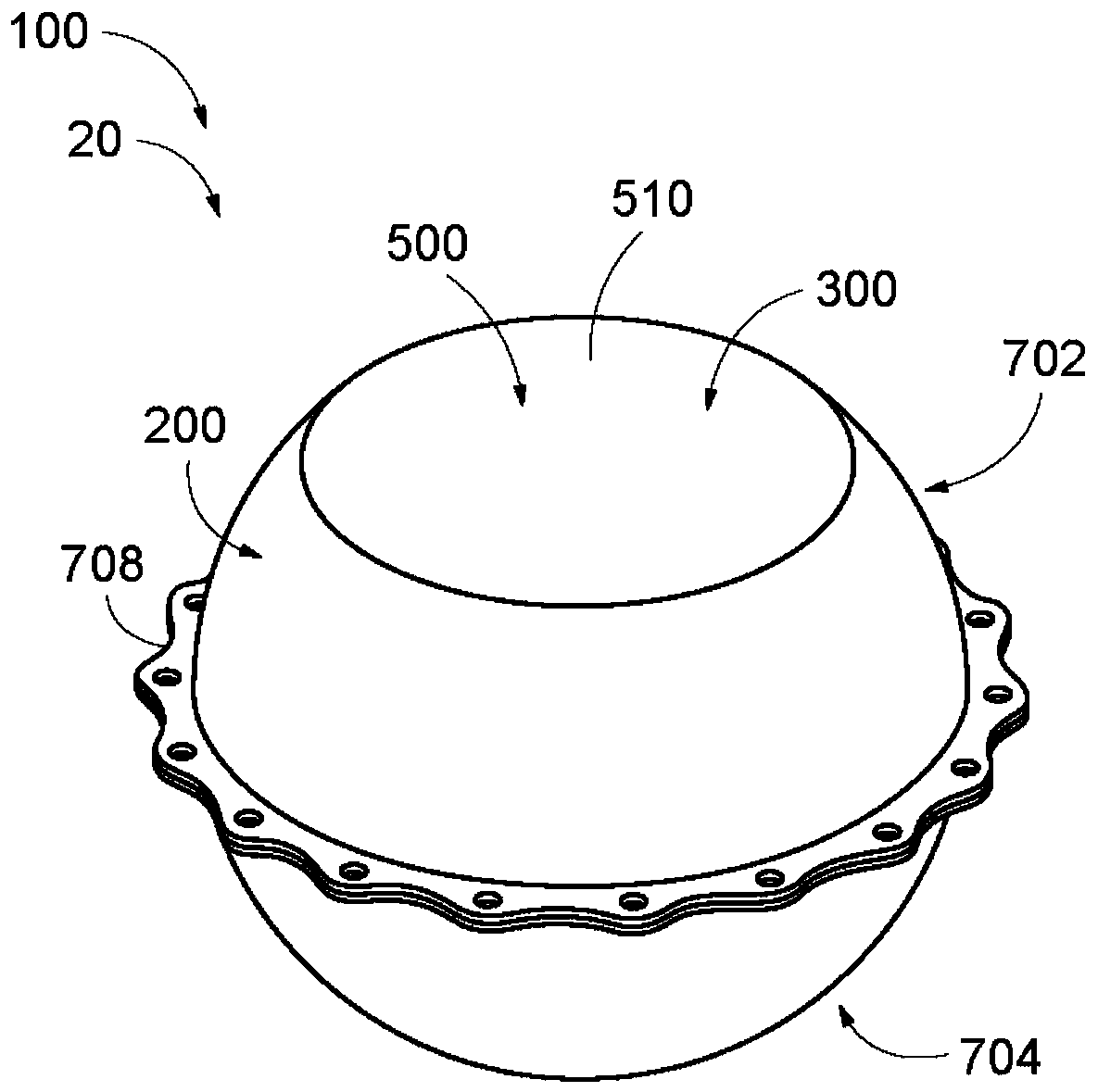
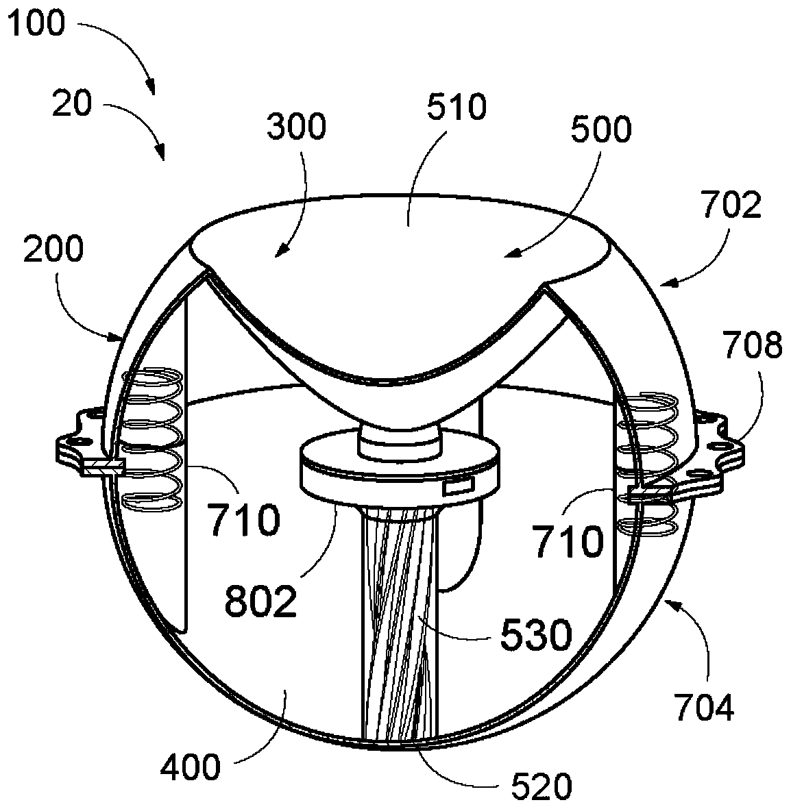
[0022] figure 1 is a schematic cross-sectional view representing a particular heat transfer device 100 according to the present disclosure. In some examples, heat transfer device 100 may be referred to as a heat transfer bulb (XTS). Such as figure 1 As schematically shown in , the heat transfer device 100 at least includes an outer wall 200 , an inner wall 300 and an inner volume 400 ...


PUM


Abstract

The invention relates to heat transfer devices and methods for enclosing a heat source and facilitating convective heat transfer from the heat source. The heat transfer device includes an outer wall having an outer surface exposed to an environment of the heat transfer device and defining an outer shape of the heat transfer device, and an inner wall defining a flow passage through the heat transfer device. The outer wall and the inner wall collectively define an internal volume that is configured to house the heat source. The flow passage comprises an inlet configured to receive a fluid from the environment, and an outlet configured to exhaust the fluid from the flow passage that comprises a core region extending between the inlet and the outlet and configured to deliver the fluid from theinlet to the outlet and allow heat to exchange between the fluid within the core region and the internal volume.

Description

technical field [0001] The present disclosure relates to unique heat transfer devices, and more particularly to heat transfer devices for attaching heat and / or cooling sources and facilitating convective heat transfer from or to such sources. Background technique [0002] Some devices (especially electronic devices) generate / release heat, in some cases excess heat and / or wasted heat. This heat must be properly controlled and dissipated to prevent performance degradation and / or premature failure. Therefore, the thermal interaction of any device with its environment is an important design feature to facilitate its proper function. Typically, the thermal interaction of a heat-generating device is managed by driving a coolant close to the device to absorb (in some cases evenly) generated heat away from the device. However, with existing technologies, it is difficult to cool heat-generating devices located at the perimeter of the item / body / structure due to the difficulty of dri...

Claims


Application Information

Patent Timeline
IPC IPC(8): H05K7/20
CPCH05K7/20272F28D2021/0028H01L23/46F28D1/0246F28F1/006F28F1/124F28F1/40F28F7/00F28F2275/08F28F2275/20F28F2280/00F28F2280/105F28F13/08B64D33/10B63G8/36F03D80/60H02K9/06H01L23/3677B63J2/00Y02E10/72F05B2260/201Y02T50/60B64D13/006F28D11/02H05K7/20145H05K7/20163H05K7/20236
Inventor C·C·威特E·E·布奇
Owner THE BOEING CO
Learn More