
Grinding device

A grinding and grinding wheel technology, which is applied in the field of vehicles, can solve the problems of low grinding efficiency of high-voltage cable terminals, achieve the effects of improving grinding efficiency, improving product quality, and reducing production costs

Active Publication Date: 2020-09-29
CRRC QINGDAO SIFANG CO LTD
View PDF8 Cites 3 Cited by
  • Summary
  • Abstract
  • Description
  • Claims
  • Application Information

AI Technical Summary

Problems solved by technology

[0005] The main purpose of the present invention is to provide a grinding device to solve the problem of low grinding efficiency of high-voltage cable terminals in the prior art

Method used


Image

  • Grinding device
  • Grinding device
  • Grinding device

Examples


Embodiment Construction

[0029] It should be noted that the embodiments in the application and the features in the embodiments can be combined with each other if there is no conflict. Hereinafter, the present invention will be described in detail with reference to the drawings and in conjunction with the embodiments.

[0030] It should be pointed out that the following detailed descriptions are all illustrative and are intended to provide further explanations for the application. Unless otherwise indicated, all technical and scientific terms used herein have the same meaning as commonly understood by those of ordinary skill in the technical field to which this application belongs.

[0031] It should be noted that the terms used here are only for describing specific implementations, and are not intended to limit the exemplary implementations according to the present application. As used herein, unless the context clearly indicates otherwise, the singular form is also intended to include the plural form. In...


PUM


Abstract

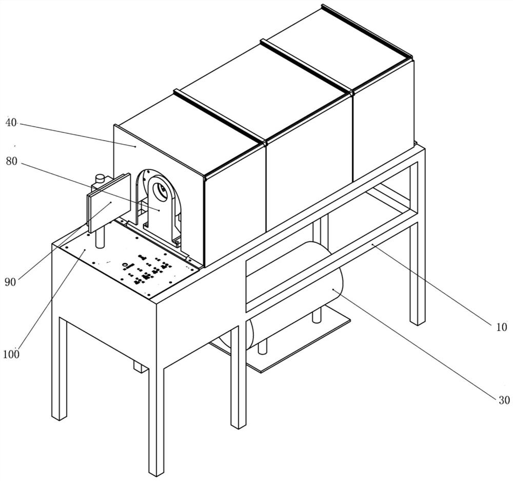
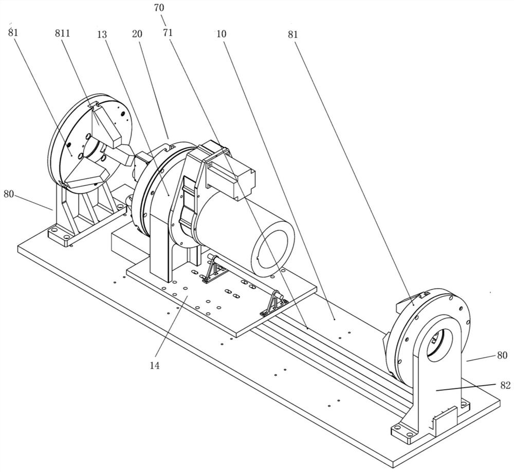
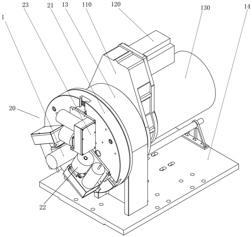
The invention provides a polishing device. The polishing device is used for polishing a to-be-polished piece, and is provided with a scheduled operating center line. The polishing device comprises a rack and a grinding mechanism; the grinding mechanism is arranged on the rack; the grinding mechanism comprises a rotating disc and grinding wheels; the grinding wheels are rotatably arranged around the axis of the grinding mechanism; a first through hole through which the to-be-polished piece penetrates is formed in the rotating disc; the center line of the first through hole coincides with the scheduled operating center line; the grinding wheels are connected with the rotating disc; the grinding wheels are movably arranged in the radial direction of the rotating disc so as to be close to or far away from the to-be-polished piece; the rotating disc is rotatably arranged around the scheduled operating center line so as to drive the grinding wheels to rotate around the to-be-polished piece,so that the to-be-polished piece is circumferentially ground; and the grinding mechanism is movably arranged in the extending direction of the scheduled operating center line so as to drive the grinding wheels to axially grind the to-be-polished piece. According to the polishing device, the problem that the polishing efficiency of a high voltage cable terminal is relatively low in the prior art issolved.

Description

Technical field [0001] The invention relates to the technical field of vehicles, and in particular to a polishing device. Background technique [0002] EMUs have gradually become the best way for short- and medium-distance travel at present, which has further shortened the distance and development between cities. As the speed of EMUs increases, the traction power of trains has gradually increased. The process of electric energy transmission is particularly critical, especially from contact Single-phase 25kV, 50Hz high-voltage power directly received by the network. The high-voltage parts to be polished on the train serve as the connection between the pantograph, high-voltage equipment and the traction transformer, and are the main trunk line for vehicle power transmission. Once a failure occurs, the vehicle will inevitably lose power and wait for rescue. [0003] At present, the processing and assembling process of the terminal of the high-pressure part to be polished is very comp...

Claims


Application Information

Patent Timeline
Patent Type & Authority Patents(China)
IPC IPC(8): B24B19/00B24B41/06B24B41/02B24B47/12B24B47/22B24B51/00B24B55/02
CPCB24B19/00B24B41/02B24B41/06B24B47/12B24B47/22B24B51/00B24B55/02
Inventor 李翔飞邴晨阳黄召明常杰高月欣
Owner CRRC QINGDAO SIFANG CO LTD
Learn More