
A high-performance final output system for high-power RF sources

An output system and radio frequency output technology, applied in the field of radio frequency sources, can solve problems such as poor performance, increased heat dissipation, increased cost, etc., and achieve the effects of avoiding the use of PCB, reducing operating temperature, and small dielectric loss

Active Publication Date: 2021-08-27
武汉市福志成科技有限责任公司
View PDF0 Cites 0 Cited by
  • Summary
  • Abstract
  • Description
  • Claims
  • Application Information

AI Technical Summary

Problems solved by technology

Each measure doubles or even dozens of times increases the cost and material procurement cycle, and these measures did not jump out of the traditional PCB + component architecture system, and did not fundamentally solve the problem after paying expensive costs. Reliability is still unsatisfactory
[0005] In addition, in addition to reliability and cost issues, the architecture system of PCB+ components is used in the radio frequency field above the kilowatt level, with large discreteness and poor performance
Because the system of PCB+components is suitable for mass production, but it lacks precise adjustment methods one by one, the parameters of PCB and components are discrete. In small and medium power electronic products, these discreteness can be tolerated by increasing the design margin. However, for kilowatt-level or even dozens of kilowatt-level radio frequency products, increasing the design margin will bring about doubled cost increases, reduced overall machine efficiency, and increased heat dissipation.

Method used


Image

  • A high-performance final output system for high-power RF sources
  • A high-performance final output system for high-power RF sources
  • A high-performance final output system for high-power RF sources

Examples


Embodiment 1

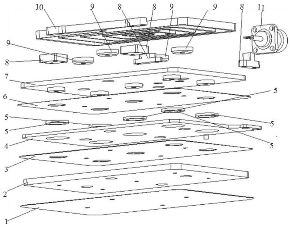
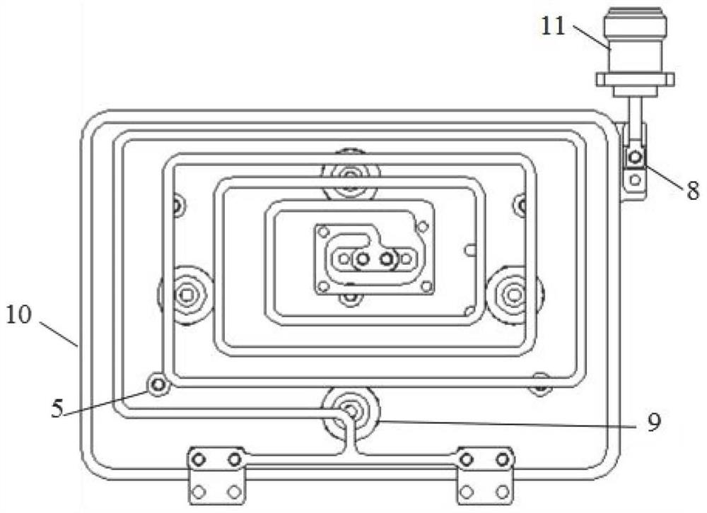
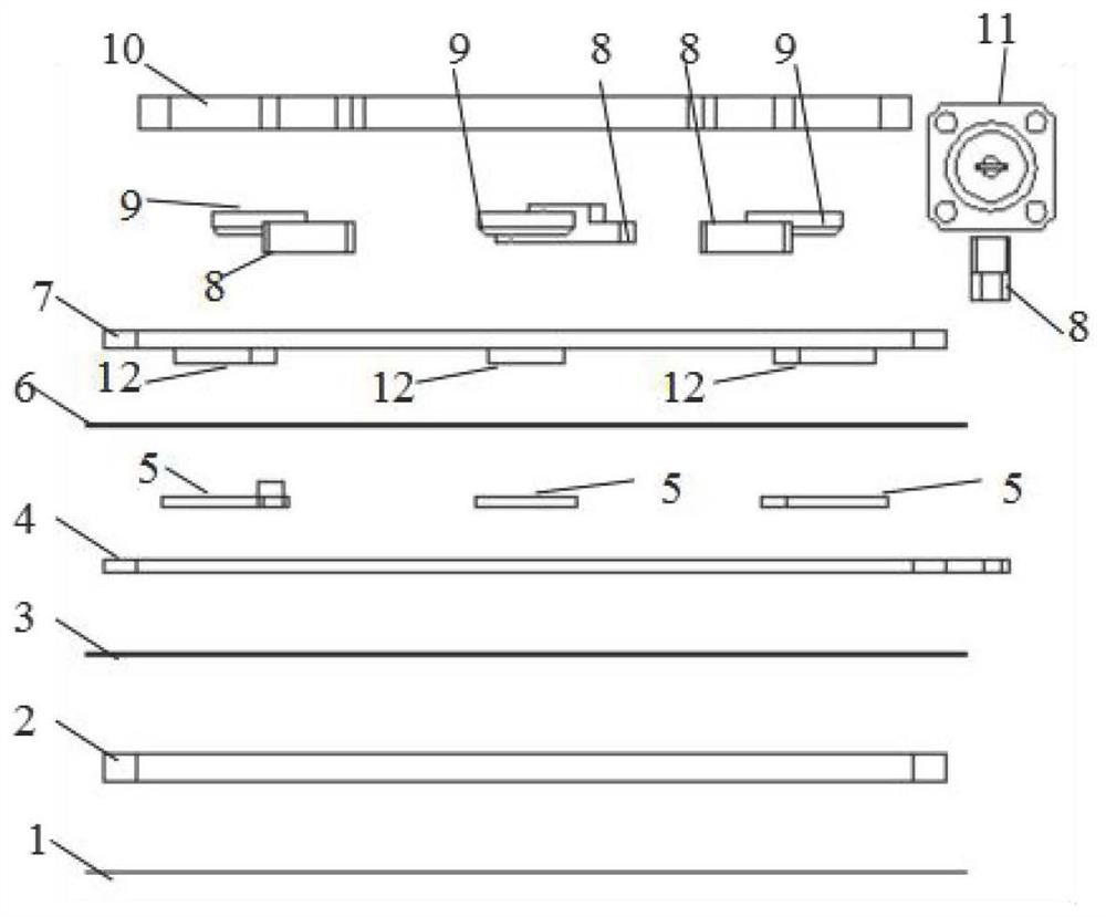
[0036]A high-performance final output system for a high-power radio frequency source, including: a cavity, an inductor and a capacitor arranged in the cavity, and the capacitor includes a first capacitor and a second capacitor; one end of the inductor is externally connected to the power of the high-power radio frequency source amplifier, the other end of the inductance is connected to the first capacitor and one end of the second capacitor respectively, the other end of the first capacitor is the radio frequency output end, and the other end of the second capacitor is grounded, such as Figure 1 ~ Figure 3 As shown, both the first capacitor and the second capacitor are plate capacitors (consisting of the capacitor bottom plate 2, the second capacitor top plate 4 and the first capacitor top plate 7), and the inductor 10 is a planar spiral metal strip. Wherein, the plate corresponding to the other end of the second capacitor is the cavity bottom plate of the cavity, and the cavi...


PUM


Abstract

The invention relates to a high-performance final stage output system for a high-power radio frequency source, comprising: a cavity, an inductor and a capacitor arranged in the cavity, the capacitor includes a first capacitor and a second capacitor; one end of the inductor is externally connected to a high-power radio frequency The other end of the inductor is connected to the first capacitor and one end of the second capacitor respectively, the other end of the first capacitor is the RF output end, the other end of the second capacitor is grounded, the first capacitor and the second capacitor are both As for the plate capacitor, the inductance is a plane spiral metal strip, and the plate corresponding to the other end of the second capacitor is the cavity bottom plate of the cavity, and the cavity bottom plate is grounded. The present invention uses metal plate capacitors instead of small-sized capacitors on the PCB and adopts plane spiral metal strips as inductors, avoiding the use of PCBs, the loss of the plate capacitors and inductors is small, there is no heat accumulation point, and the heat conduction is fast and extremely The reliability of the final high-power radio frequency capacitor is greatly improved, and the cost is low.

Description

technical field [0001] The invention relates to the technical field of radio frequency sources, in particular to a high-performance final output system for high-power radio frequency sources. Background technique [0002] As an energy source for generating plasma, high-power radio frequency sources are widely used in many fields such as semiconductor manufacturing, coating, high-power lasers, and basic scientific research. Commonly used RF output powers range from hundreds of watts to tens of kilowatts. Although high-power RF sources have been developed for decades, there are still prominent shortcomings of high cost and insufficient reliability. The root cause of low reliability is that the high-power final stage still uses the traditional electronic product system, that is, the use of printed circuit boards (PCBs) and general components. [0003] After several decades of development, the electronic product system system represented by printed circuit board (PCB) and gener...

Claims


Application Information

Patent Timeline
Patent Type & Authority Patents(China)
IPC IPC(8): G06K19/07G06K19/077
CPCG06K19/0723G06K19/0772
Inventor 甄德海左世雄杜晨
Owner 武汉市福志成科技有限责任公司
Learn More