
A tank welding rod unwinding and cutting mechanism

A technology of unwinding mechanism and welding rod, which is applied in the direction of manufacturing tools and other manufacturing equipment/tools, etc., which can solve the problems of excessive unwinding of welding rods, loose welding rod coils, inconsistent lengths of cut sections of welding rods, etc., to achieve reasonable structural design and improve automation degree of effect

Active Publication Date: 2019-09-03
ZHEJIANG TANKPRO IND
View PDF4 Cites 0 Cited by
  • Summary
  • Abstract
  • Description
  • Claims
  • Application Information

AI Technical Summary

Problems solved by technology

The existing electrode unwinding mechanism is complicated in structure and cumbersome to operate. It is difficult to quickly and efficiently unwind the electrode accurately. During the unwinding process, the electrode often causes excessive unwinding of the electrode due to the pulling inertia, resulting in the unwinding of the electrode. During the process, the entire electrode coil will become loose, which will affect the efficient and stable unwinding and transmission of the electrode. During the transmission process of the existing electrode, it is difficult to transmit the electrode at a fixed length intermittently according to the needs of actual use, often causing the electrode to be cut into sections. The length of the welding rod is inconsistent, which affects the normal use of the welding rod for the welding of the tank body. The inaccurate cutting of the welding rod will easily increase the loss of the welding rod. The welding rod cannot be cut off sufficiently and efficiently, which makes it difficult for the welding rod to be unwound continuously and smoothly, which cannot meet the needs of processing and use

Method used


Image

  • A tank welding rod unwinding and cutting mechanism
  • A tank welding rod unwinding and cutting mechanism
  • A tank welding rod unwinding and cutting mechanism

Examples


Embodiment Construction

[0019] In order to further describe the present invention, the specific implementation of a tank electrode unwinding and cutting mechanism will be further described below in conjunction with the accompanying drawings. The following examples are explanations of the present invention and the present invention is not limited to the following examples.

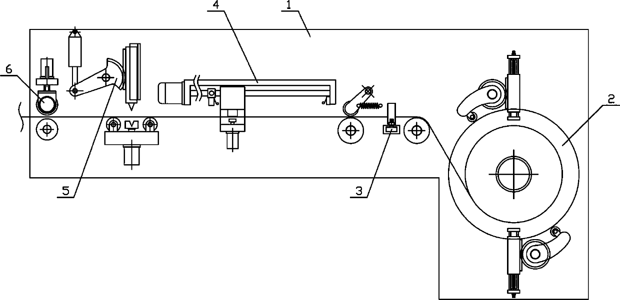
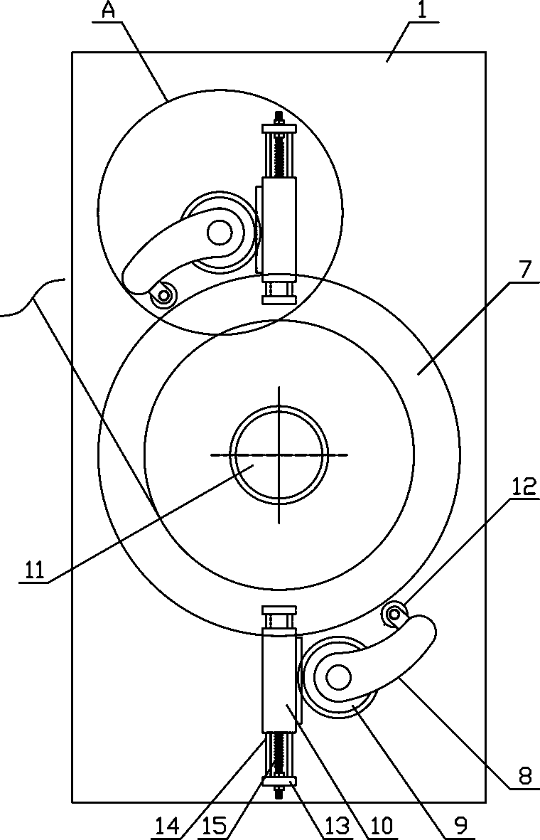
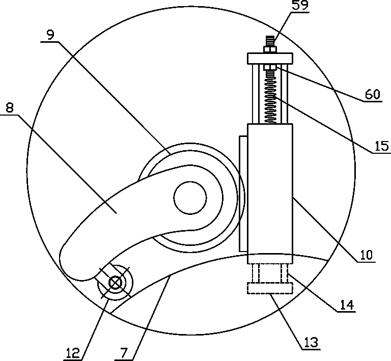
[0020] Such as figure 1 As shown, a kind of tank electrode unwinding and cutting mechanism of the present invention comprises a strip cutting support 1, an unwinding mechanism 2, a limit mechanism 3, a material pulling mechanism 4, a pressing and cutting mechanism 5 and a blanking mechanism 6. The unwinding mechanism 2, the limiting mechanism 3, the pulling mechanism 4, the pressing and cutting mechanism 5 and the unloading mechanism 6 are fixedly arranged on one side of the strip cutting support 1 in sequence along the horizontal direction. Such as figure 2 , image 3 As shown, the unwinding mechanism 2 of the present inventio...


PUM


Abstract

The invention discloses a working method for a welding rod conveying and cutting mechanism, and belongs to the field of auxiliary processing machinery of water purification equipment. The welding rodconveying and cutting mechanism comprises an unwinding mechanism body, a limiting mechanism body, a material pulling mechanism body, a pressing and cutting mechanism body and a discharging mechanism body which are sequentially and fixedly arranged on one side of a strip cutting support in the horizontal direction; damping rotating wheels are vertically connected to one ends of pressure plate rotating rods on the two sides of an unwinding turntable along the side of the unwinding turntable in a rotating mode; limiting guide shafts are vertically connected to one sides of the upper parts of adjusting guide plates on the two sides of a limiting support in a rotating mode; a material pulling support is arranged on a translation guide rod in a sliding mode in the horizontal direction; a material cutting knife groove is horizontally formed in the upper side of a material cutting bearing plate at the output end of a material bearing air cylinder; and a lifting cutter matched with the materialcutting knife groove is horizontally and fixedly arranged at the lower end of a material cutting pressing plate in a material cutting support. The working method has the advantages that the structural design is reasonable, a welding rod can be stably and accurately unwound and conveyed and can be cut off efficiently, the automation degree of unwinding processing of the welding rod is improved, and the processing and using requirements are met.

Description

technical field [0001] The invention belongs to the field of water purification equipment processing auxiliary machinery, and in particular relates to a welding rod unwinding and cutting mechanism for a tank body, which is mainly used in the welding processing field of water purifier equipment production. Background technique [0002] The tap water for daily drinking has gone through a variety of cleaning, sterilization and disinfection methods, and the water quality testing at the factory can meet the national hygiene standards. However, after long pipelines and secondary pressurized water tanks, some pipelines have been in disrepair for a long time, and the water pipes are leaking. , This will cause water pollution. At the same time, in the secondary pressurized water tank, because the water tank has not been cleaned and disinfected for a long time, there will be rust and other pollution in the water tank, which will cause rust in our drinking water. Pathogenic microorgani...

Claims


Application Information

Patent Timeline
Patent Type & Authority Patents(China)
IPC IPC(8): B23P23/04B23P23/06
CPCB23P23/04B23P23/06
Inventor 张家晖
Owner ZHEJIANG TANKPRO IND
Learn More