Water well landfill method
A water well and cement technology, applied in excavation, construction, infrastructure engineering, etc., can solve the problems of secondary pollution of groundwater sources in water wells, lack of landfill safety performance, etc., to avoid secondary construction and investment, save manpower, and fill The effect of fast buried efficiency
- Summary
- Abstract
- Description
- Claims
- Application Information
AI Technical Summary
Problems solved by technology
Method used
Image
Examples
Embodiment 1
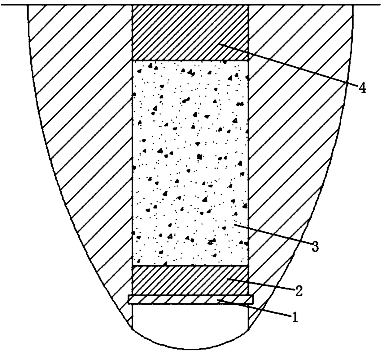
[0022] Embodiment one: if figure 1 As shown, when the water well is in non-cultivated land, the water well landfill method includes the following steps:
[0023] Step 1, build a support plate 1, and fix the prefabricated support plate 1 on the inner wall of the well;
[0024] Step 2, the lower part of the water well is buried, and the lower part of the cement landfill body 2 is poured inside the water well at the upper end of the support plate, and solidified;
[0025] Step 3, the middle section of the water well is buried, and the middle section cement landfill body 3 is poured inside the water well at the upper end of the lower section cement landfill body 2, and solidified;
[0026] Step 4: Filling the upper part of the water well, pouring the upper cement landfill body 4 inside the water well at the upper end of the middle cement landfill body 3, and solidifying.
[0027] Wherein, the height of the upper end of the upper cement landfill body 4 can be flush with the groun...
Embodiment 2
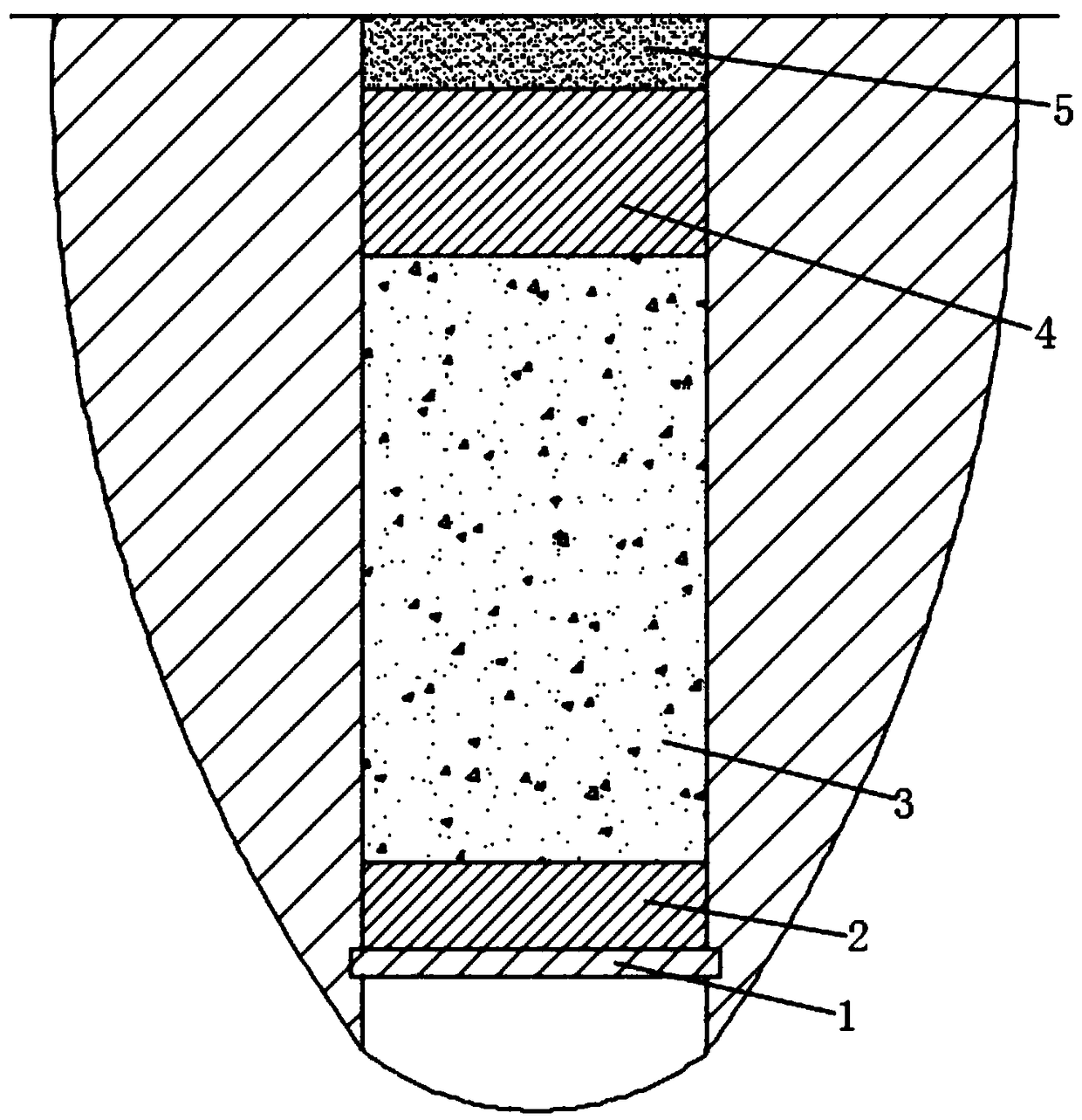
[0033] Embodiment two: if figure 2 As shown, the water well is in the cultivated land, and the water well landfill method comprises the following steps:
[0034] Step 1, build a support plate 1, and fix the prefabricated support plate 1 on the inner wall of the well;
[0035] Step 2, the lower part of the water well is buried, and the lower part of the cement landfill body 2 is poured inside the water well at the upper end of the support plate, and solidified;
[0036] Step 3, the middle section of the water well is buried, and the middle section cement landfill body 3 is poured inside the water well at the upper end of the lower section cement landfill body 2, and solidified;
[0037] Step 4, the upper part of the water well is buried, and the upper cement landfill body 4 is poured inside the water well at the upper end of the middle cement landfill body 3, and solidified;
[0038] Step 5, soil filling, the topsoil layer of the excavated land is filled in the soil body 5 i...
PUM
| Property | Measurement | Unit |
|---|---|---|
| Height | aaaaa | aaaaa |
| Height | aaaaa | aaaaa |
| Height | aaaaa | aaaaa |
Abstract
Description
Claims
Application Information
 - Generate Ideas
- Intellectual Property
- Life Sciences
- Materials
- Tech Scout
- Unparalleled Data Quality
- Higher Quality Content
- 60% Fewer Hallucinations
Browse by: Latest US Patents, China's latest patents, Technical Efficacy Thesaurus, Application Domain, Technology Topic, Popular Technical Reports.
© 2025 PatSnap. All rights reserved.Legal|Privacy policy|Modern Slavery Act Transparency Statement|Sitemap|About US| Contact US: help@patsnap.com


