
Machining unit

A technology for processing units and workpieces, applied in metal processing, metal processing equipment, workpieces, etc., can solve the problems of high cost, prolong the takt time of processing workpieces, etc., and achieve the effect of long life and effective effect of multiple bristles.

Inactive Publication Date: 2018-02-27
MAUSER WERKE OBERNDORF MASCHENBAU
View PDF2 Cites 0 Cited by
  • Summary
  • Abstract
  • Description
  • Claims
  • Application Information

AI Technical Summary

Problems solved by technology

[0005] A further disadvantage is that, especially in complex machining of graded workpieces, in order to ensure dimensional stability, the grinding disc needs to be reconditioned cyclically, which is expensive and greatly prolongs the working time on the grinding device. Takt time of machining workpiece

Method used


Image

  • Machining unit
  • Machining unit
  • Machining unit

Examples


Embodiment Construction

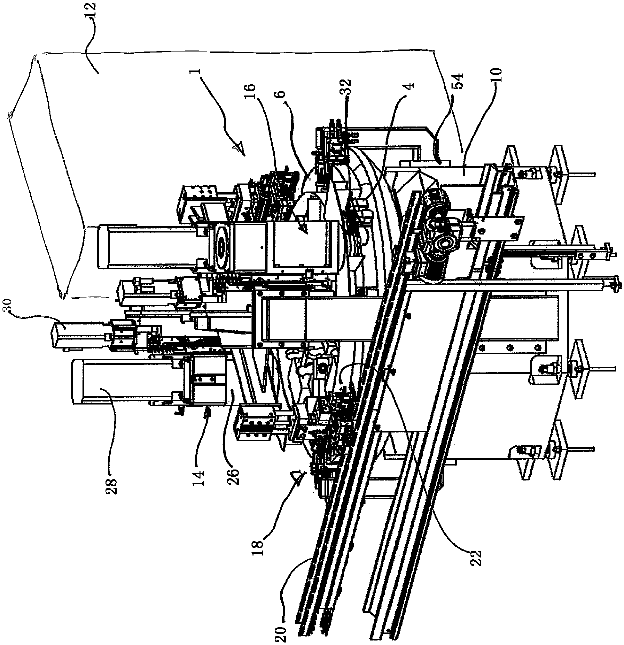
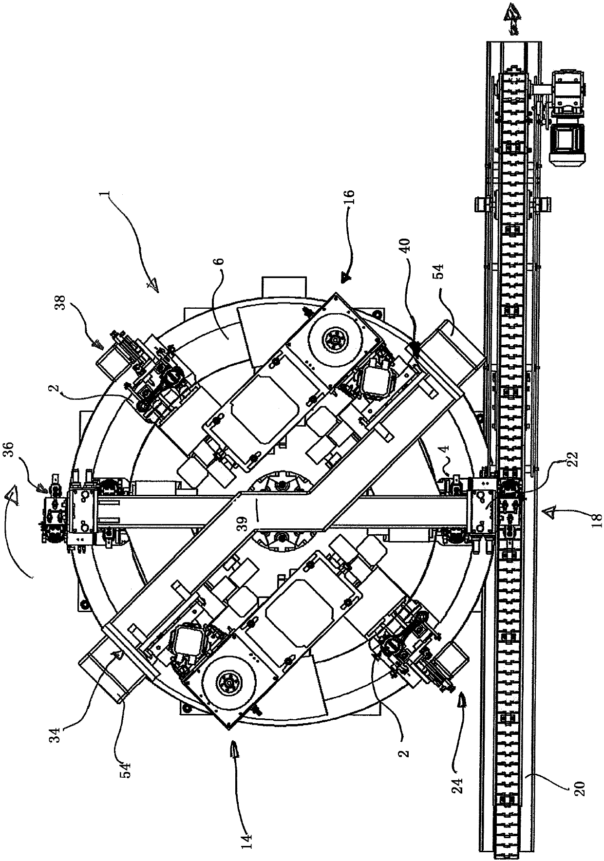
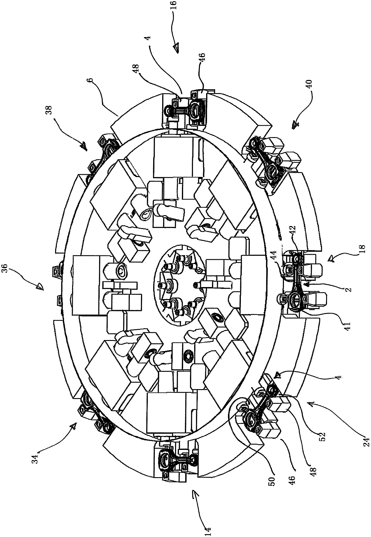
[0043] figure 1 Shown according to the present invention for the connecting rod (see figure 2 ) in a three-dimensional view of a first embodiment of a machining unit 1 for planar machining, the connecting rod is held on a rotatably supported NC circular table 6 by means of a clamping device also called a clamping nest. This NC circular table 6 is mounted rotatably on a frame 10 of the processing unit 1 and can be driven clockwise or cyclically via the machine control. In the exemplary embodiment shown, processing unit 1 has a total of eight processing stations, which will be explained in greater detail below. Two of the machining stations are designed as finishing stations 14 , 16 , at which the planes of the connecting rods are finished. The loading and unloading of the connecting rods is done via the loading and unloading workstation 18 . This loading and unloading station has a conveyor belt 20 via which the connecting rods to be processed are conveyed and discharged in...


PUM


Abstract

Disclosed is a machining unit for machining an end face of a workpiece. The machining unit has a work table which rotates or is clocked during the machining process.

Description

technical field [0001] The invention relates to a machining unit for machining a flat or end face of a workpiece, in particular a connecting rod. Background technique [0002] Finishing of the flat / end faces of the connecting rod is conventionally carried out by grinding, that is to say without defined stock removal. A grinding device is used here, in which two grinding disk sections are arranged at a distance from one another, so that, for example, both end faces of a connecting rod can be machined simultaneously. Such a grinding device is known from DE 10 2012 024 248 A1. In this solution, the machining of the multi-stage connecting rod takes place with the aid of two graded grinding discs, which together define a grinding space in which the workpiece to be machined is inserted , in the present case a connecting rod, in order to achieve two-sided plane machining. [0003] In such a device for step grinding, in combination with the design of the grinding disc and the gri...

Claims


Application Information

Patent Timeline
Patent Type & Authority Applications(China)
IPC IPC(8): B23Q7/00B23Q7/02B23Q39/04
CPCB23C2215/245B23Q7/007B23Q7/02B23Q39/046
Inventor 沃尔夫冈·伦普格哈德·劳施
Owner MAUSER WERKE OBERNDORF MASCHENBAU
Learn More