Water treatment system and water treatment method
A water treatment system and water treatment technology, applied in natural water treatment, water/sewage treatment, water treatment parameter control, etc., can solve huge energy and cost problems
- Summary
- Abstract
- Description
- Claims
- Application Information
AI Technical Summary
Problems solved by technology
Method used
Image
Examples
Embodiment approach 1
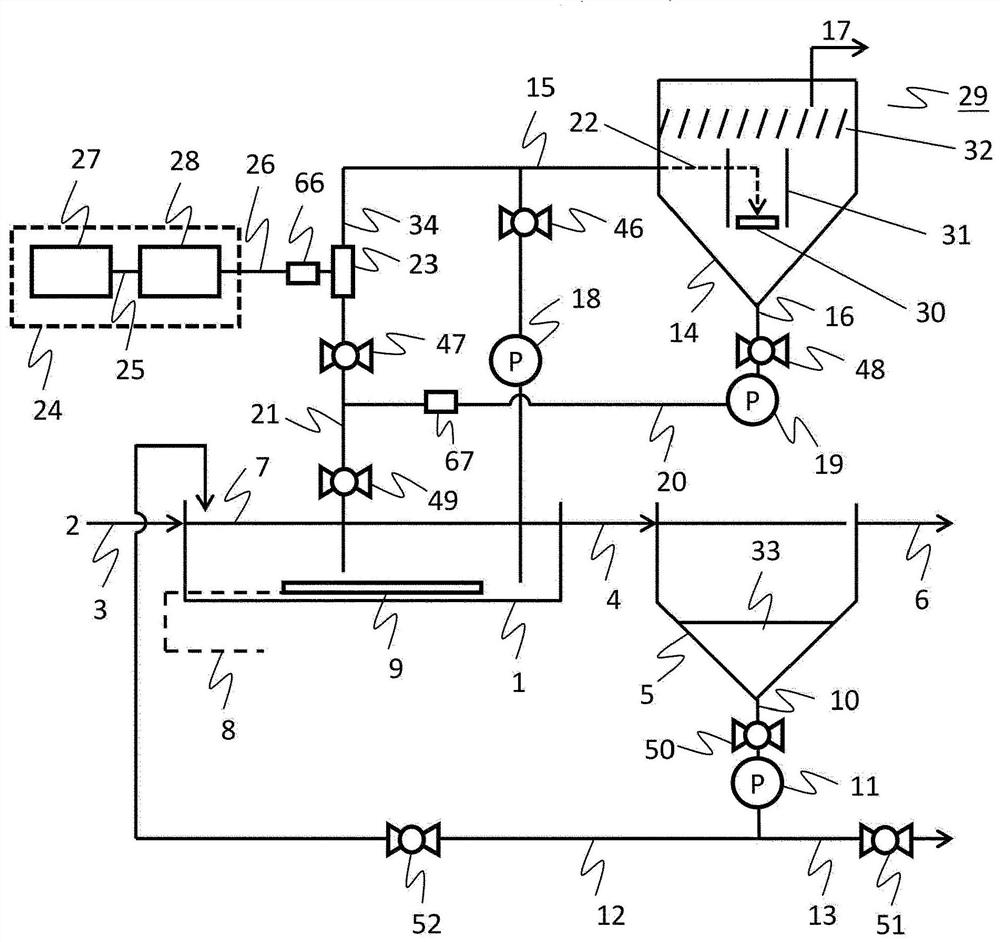
[0041] figure 1 It is a schematic diagram which shows an example of the water treatment system concerning Embodiment 1. The water treatment system uses the standard activated sludge method in the biological treatment process.
[0042] The water treatment system includes structural elements such as the aeration tank 1 as an example of a microbial treatment unit configured to treat water using microorganisms. The aeration tank 1 contains aerobic microorganisms that can utilize organic matter as a substrate. Moreover, the aeration tank 1 is connected with the waste water introduction path 3 which accommodates the waste water 2, and the outflow path 4 which accommodates the outflow water from the aeration tank 1. As shown in FIG. In addition, the outflow path 4 is also connected to the sedimentation tank 5 , and the outflow water from the aeration tank 1 is transferred to the sedimentation tank 5 . The sedimentation tank 5 is connected to a treated water discharge channel 6 , a...
Embodiment approach 2
[0163] Figure 11 It is an example of the apparatus structure of this invention when "standard activated sludge process" is applied to a biological treatment process.
[0164] exist Figure 11 Among them, the sludge transfer pipe 15 is connected to the sludge return pipe 12 . In addition, in Figure 11 Among them, the sludge transfer pump 18 is not provided. Otherwise with figure 1 same.
[0165] In Embodiment 2, the separated sludge 33 accumulated in the settling tank 5 , that is, microorganisms flowing out from the aeration tank 1 is transferred to the ozone reaction tank 14 to perform ozone treatment. When the sludge transfer process starts, the valve 46 on the sludge transfer pipe 15 is opened, and the microbial mixture 7 flowing through the sludge return pipe 12 is transferred to the ozone reaction tank 14 through the sludge transfer pipe 15 .
[0166] The transfer amount can be managed in the same way as in the first embodiment. Other operations are the same as in...
Embodiment approach 3
[0168] Figure 12 This is an example of the device structure of the present invention when the "biofilm method" is applied to the biological treatment process. exist Figure 12 In the aeration tank 1, a microbial carrier 37 is dropped. Besides that, with Figure 11 (Embodiment 2) is the same.
[0169] The purpose of the microbial carrier thrown into the aeration tank is to attach microorganisms to the surface and maintain a high biomass in the aeration tank. Such a biological treatment method is generally called "biofilm method". In the case of not adding a carrier, that is, in the case of the "standard activated sludge method" described in Embodiment 1, the floating microorganisms use the organic matter in the wastewater to purify the wastewater, but in the biofilm method, after passing The difference is seen in the purification of microorganisms attached to and fixed on the surface of the carrier. However, it is common to purify wastewater using microorganisms. In addi...
PUM
 Abstract
Description
Claims
Application Information
 - R&D Engineer
- R&D Manager
- IP Professional
- Industry Leading Data Capabilities
- Powerful AI technology
- Patent DNA Extraction
Browse by: Latest US Patents, China's latest patents, Technical Efficacy Thesaurus, Application Domain, Technology Topic, Popular Technical Reports.
© 2024 PatSnap. All rights reserved.Legal|Privacy policy|Modern Slavery Act Transparency Statement|Sitemap|About US| Contact US: help@patsnap.com


