
Z type ejector core pulling mechanism

A technology of core-pulling mechanism and ejector pin, which is applied in the field of injection molds for plastic parts, and can solve problems affecting the appearance quality of products, affecting the optical effect of light guides, and affecting the service life of core-pulling molds, etc.

Active Publication Date: 2019-12-17
HASCO VISION TECHNOLOGY CO LTD
View PDF4 Cites 0 Cited by
  • Summary
  • Abstract
  • Description
  • Claims
  • Application Information

AI Technical Summary

Problems solved by technology

In this way, the core-pulling slider must be made very large, and there will be a lot of core-pulling marks on the formed product, which is not accepted because it affects the appearance quality of the product. If it is a molded light guide, it will even affect the optical effect of the light guide.
When the slope of the parting surface is very large, the core-pulling slider will have sharp corners, which will seriously affect the service life of the mold core-pulling

Method used


Image

  • Z type ejector core pulling mechanism
  • Z type ejector core pulling mechanism
  • Z type ejector core pulling mechanism

Examples


Embodiment Construction

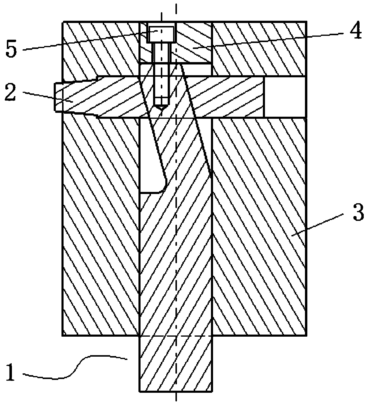
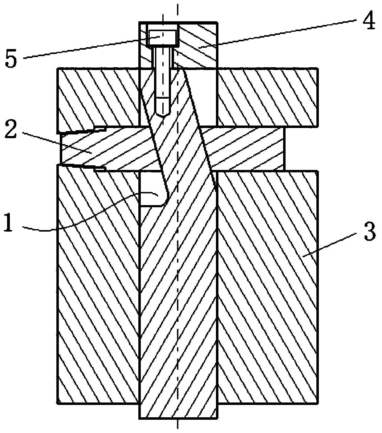
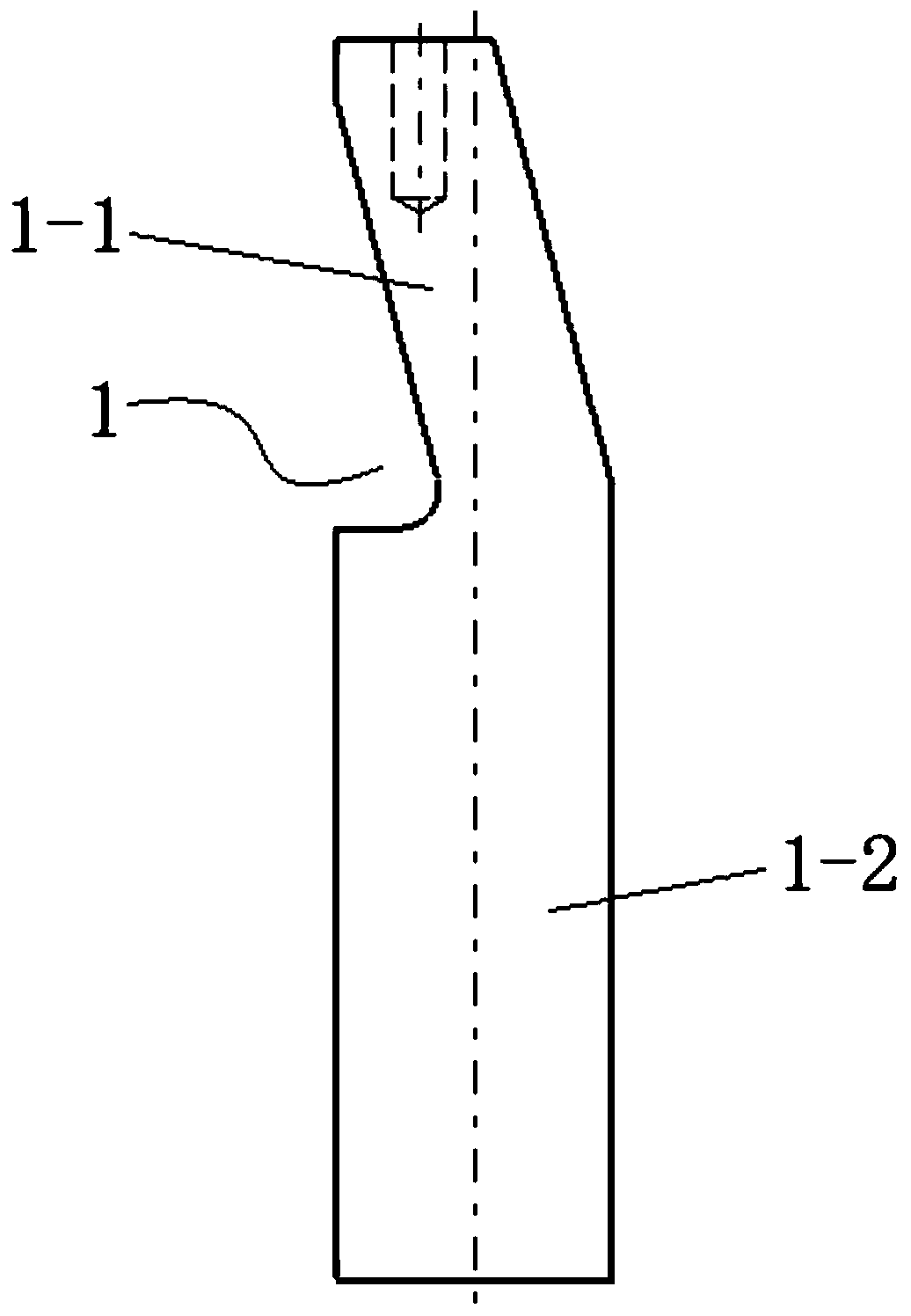
[0024] The invention discloses a Z-shaped ejector core-pulling mechanism, such as figure 1 As shown, the ejector rod 1 and the slide block 2 are included, and the ejector rod is vertically installed in a ejector rod installation hole of a base part 3 . The push rod is divided into upper and lower parts, namely a neck 1-1 and a body 1-2, and the push rod slides up and down with the base part through the body. The cross-sectional area of ​​the neck is smaller than that of the body, and the neck is arranged at an inclination of upper left and lower right (or lower left and upper right). The projection of the neck on the horizontal plane does not exceed the body. The slider extends left and right and is installed in the chute of the base component, and slides and cooperates with the base component left and right, and the chute is a left and right through groove. The slider is conformably fitted on the neck through the oblique hole 2-1 in the middle, and is slidably engaged with ...


PUM


Abstract

The invention relates to a Z-shaped ejection rod core pulling mechanism which comprises an ejection rod and a sliding block; the ejection rod is vertically mounted in an ejection rod mounting hole of a basic part; the ejection rod is divided into an upper part and a lower part, namely, a neck and a body; the ejection rod is vertically and slidingly matched with the basic part through the body; the cross section area of the neck is less than that of the body; the neck is obliquely arranged in an upper left and lower right manner or in a lower left and upper right manner; the sliding block is arranged in a sliding groove of the basic part in a left-right extending manner, and is matched with the basic part in a left-right sliding manner; and the sliding block sleeves the neck through an oblique hole located in the middle of the sliding block in a shape follow-up manner, and is slidingly matched with the neck. The sliding block can be arranged freely, and is not required to be relevant to a parting surface, the Z-shaped ejection rod core pulling mechanism is simple in structure and is small and exquisite, core pulling traces can be reduced significantly, the appearance quality of an injection moulding product is improved, and the Z-shaped ejection rod core pulling mechanism is very practical for injection molding of large-size complicated plastic parts.

Description

technical field [0001] The invention relates to a core-pulling mechanism for injection molds, especially suitable for injection molds of plastic parts with large volume and complicated structure. Background technique [0002] Part of the surface of the core-pulling slider in all existing car lamp plastic molds must be a parting surface, because only in this way can the product be released from the mold. Therefore, when the parting surface of the product is far away from the structure that needs to be core-pulled, the core-pulling slider must start from the undercut to the end of the parting surface no matter whether the inclined guide pillar core-pulling structure or the inclined roof structure is used. In this way, the core-pulling slider must be made very large, and there will be a lot of core-pulling marks on the formed product, which is not accepted because it affects the appearance quality of the product. If it is a molded light guide, it will even affect the optical ef...

Claims


Application Information

Patent Timeline
Patent Type & Authority Patents(China)
IPC IPC(8): B29C45/33
CPCB29C45/33
Inventor 张珂
Owner HASCO VISION TECHNOLOGY CO LTD
Learn More