
LED optical engine module

A light engine and LED light board technology, applied in the field of lighting, can solve problems such as difficult LED heat dissipation, uncompact structure, unfavorable radiator heat dissipation, etc., and achieve the effect of convenient installation of LED light boards and simple structure

Pending Publication Date: 2017-11-14
HE SHAN LIDE ELECTRONICS ENTERPRISE CO LTD
View PDF7 Cites 0 Cited by
  • Summary
  • Abstract
  • Description
  • Claims
  • Application Information

AI Technical Summary

Problems solved by technology

The power supply is set independently from the LED downlight, the structure is not compact, the installation is inconvenient, and the power supply needs to be fixed separately; the power supply is connected to the tail of the radiator, which is not conducive to the heat dissipation of the radiator
The main defect of the above two power supply setting methods is: when the power supply is damaged, more professional personnel are required to replace the power supply, so as to avoid the mismatch between the power supply and the LED light source
Of course, there are also LED light engine modules that combine the power supply and LED light source together, but the existing LED light source is generally installed in the box of the LED light engine module, which is not easy to dissipate heat from the LED, which seriously affects the life of the LED.

Method used


Image

  • LED optical engine module
  • LED optical engine module
  • LED optical engine module

Examples


Embodiment Construction

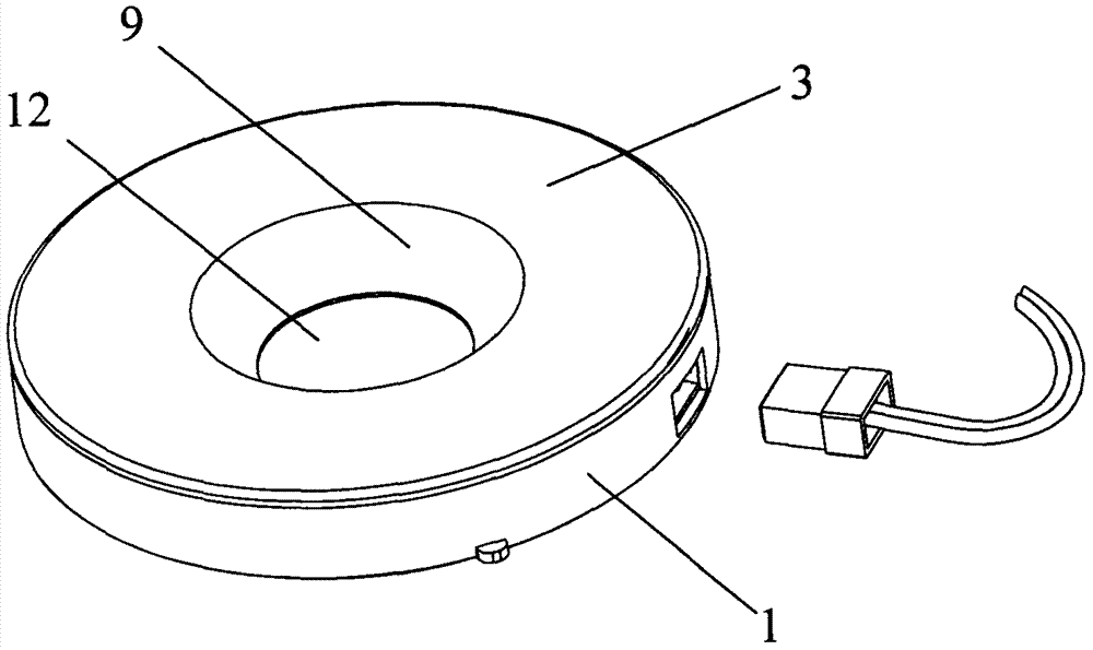
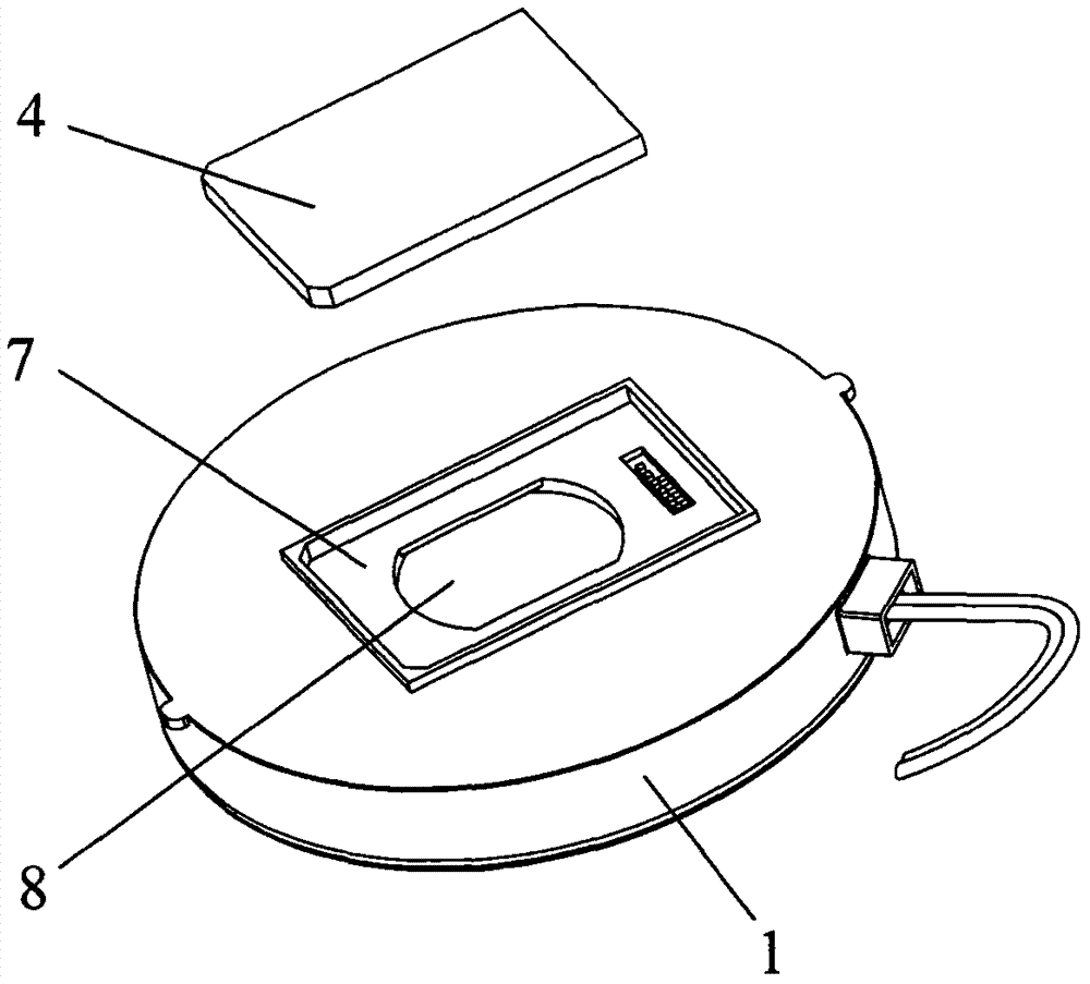
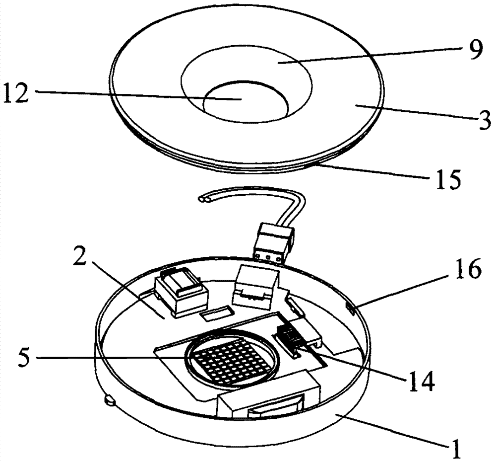
[0024] refer to figure 1 Referring to the preferred embodiment of the present invention shown in FIG. 5 , an LED light engine module includes a box body 1, a power supply module 2 disposed in the box body 1, a box cover 3 that covers the box body 1, and an LED light engine module. The lamp board 4, the LED lamp board 4 is a plurality of SMD LEDs 5 welded on the circuit substrate 6, the bottom of the box body 1 is provided with a concave cavity 7 that is concave from the bottom of the box body 1 to the inside of the box body 1, and the concave cavity The middle part of 7 is provided with a through hole 8 through the box body 1, the circuit substrate 6 of the LED lamp board 4 is set in the concave cavity 7 at the bottom of the box body 1, and the LED5 of the LED lamp board 4 is accommodated in the through hole 8 of the box body 1 , wherein the coverage of the through hole 8 is smaller than the coverage of the concave cavity 7, so that the circuit substrate 6 of the LED lamp boar...


PUM


Abstract

The invention discloses an LED optical engine module which comprises a box body, a power module, a box cover and an LED lamp panel, wherein the power module is arranged in the box body; the box body is covered by the box cover; and a circuit substrate where a plurality of LEDs are arranged serves as the LED lamp panel. The LED optical engine module is characterized in that a concave cavity which is sunken from the bottom surface of the box body towards the interior of the box body is formed in the bottom of the box body; a through hole which penetrates through the box body is formed in the middle of the concave cavity; the circuit substrate of the LED lamp panel is arranged in the concave cavity formed in the bottom of the box body; the LEDs of the LED lamp panel are accommodated in the through hole of the box body; a reflection wall which is sunken downwards from the top surface of the box cover is arranged at the position, corresponding to the LEDs, of the box cover; and the height of the concave cavity formed in the bottom of the box body is less than or equal to the thickness of the circuit substrate of the LED lamp panel. The LED optical engine module disclosed by the invention has the advantages of being compact in structure, convenient to mount or replace, and easy in heat dissipation.

Description

technical field [0001] The invention relates to the lighting field, in particular to an LED light engine module with compact structure, convenient installation or replacement, and easy heat dissipation. Background technique [0002] LED lamps have many advantages such as energy saving and environmental protection, long life, high luminous efficiency, etc., and are rapidly replacing various traditional lamps. [0003] LED downlight is one of the common LED lamps, widely used in shopping malls, hotels and other places. The structure of the LED downlight generally includes a cover, a reflector, an LED light source and a radiator. The power supply is generally independent of the LED downlight body, or the power supply is connected to the tail of the radiator. Setting the power supply independently from the LED downlight has an uncompact structure and inconvenient installation, requiring an additional fixation of the power supply; connecting the power supply to the tail of the r...

Claims


Application Information

Patent Timeline
Patent Type & Authority Applications(China)
IPC IPC(8): F21V23/00F21V3/02F21V29/71F21Y115/10
CPCF21V3/02F21V23/023F21V29/71
Inventor 谢汉良江广军王开明雷雨欢冯君浩曹东兴
Owner HE SHAN LIDE ELECTRONICS ENTERPRISE CO LTD
Learn More