
Metal pattern plate manipulator pre-aligning mechanism and metal pattern plate feeding method and application

A mask and pre-alignment technology, applied in the direction of conveyors, conveyor objects, transportation and packaging, etc., can solve the problems of damaged mask, clamping and positioning speed and force can not be flexibly controlled, etc., to achieve high speed , precise positioning and clamping, and the effect of ensuring safety

Active Publication Date: 2017-10-24
SHANGHAI MICRO ELECTRONICS EQUIP (GRP) CO LTD
View PDF6 Cites 4 Cited by
  • Summary
  • Abstract
  • Description
  • Claims
  • Application Information

AI Technical Summary

Problems solved by technology

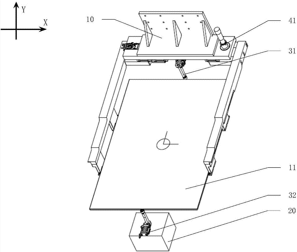
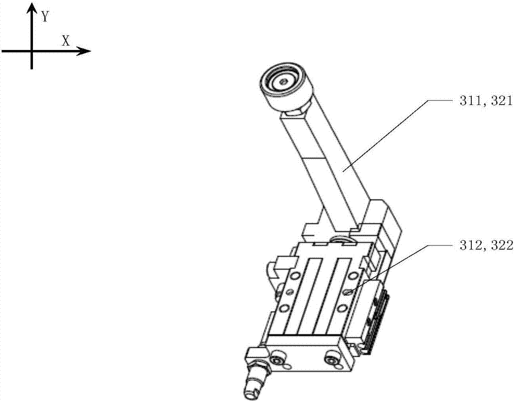
[0004] The invention provides a mask plate manipulator pre-alignment mechanism, which is used to solve the problem that the speed and force of clamping and positioning cannot be flexibly controlled in the process of loading a large-size mask plate and damage the mask plate, and improve the mask plate transmission. safety in process

Method used


Image

  • Metal pattern plate manipulator pre-aligning mechanism and metal pattern plate feeding method and application
  • Metal pattern plate manipulator pre-aligning mechanism and metal pattern plate feeding method and application
  • Metal pattern plate manipulator pre-aligning mechanism and metal pattern plate feeding method and application

Examples


Embodiment 1

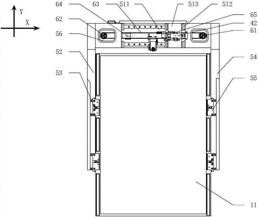
[0062] Please refer to figure 1 and image 3 , the X-direction drive mechanism includes an X-direction motor driver 41 and an X-direction cylinder driver 42, the X-direction cylinder driver 42 is arranged on the second slider 513, and the X-direction cylinder driver 42 is arranged through the guide rail on the base 10.

[0063] Please refer to image 3 , the X-direction transmission mechanism can be a belt transmission mechanism or a chain transmission mechanism, and the belt transmission mechanism is taken as an example below, and the belt transmission mechanism includes a driving wheel 61, a driven wheel 62, an intermediate winding member 63, and a first connecting member 64 and the second connecting piece 65, the driving wheel 61 and the driven wheel 62 are connected and interlocked through the intermediate winding member 63, the X-direction motor driver 41 drives the driving wheel 61, and one end of the first connecting piece 64 is connected to The other end of the left...

Embodiment 2

[0073] Please refer to Figure 7 and Figure 8 , the X-direction drive mechanism includes a left motor driver 43, a right motor driver 44, a left cylinder driver 45 and a right cylinder driver 46, and the left cylinder driver 45 and the right cylinder driver 46 are respectively arranged on two of the second slide blocks 513 , the left cylinder driver 45 and the right cylinder driver 46 are arranged on the base 10 through the guide rail.

[0074] The X-direction transmission mechanism includes a left rack and pinion transmission mechanism and a right rack and pinion transmission mechanism symmetrically arranged on the base 10, and the left and right rack and pinion transmission mechanisms are all along the X direction. Set on the base 10, the left rack and pinion transmission mechanism includes a meshing left gear 71 and a left rack 72, and the right rack and pinion transmission mechanism includes a meshing right gear 73 and a right rack 74. The left motor driver 43 is connec...


PUM


Abstract

Then invention discloses a metal pattern plate feeding method and discloses a metal pattern plate manipulator pre-aligning device adopting the method at the same time. The method comprises the steps that (a) X-direction primary positioning is conducted, specifically, a first X-direction driver drives X-direction movement assemblies to oppositely move in the X direction to enable the X-direction movement assemblies to hold a metal pattern plate located above; and (b) X-direction secondary positioning is conducted, specifically, after X-direction primary positioning is conducted, a second X-direction driver drives the X-direction movement assemblies to continue to oppositely move in the X direction to enable the X-direction movement assemblies to tightly clamp the metal pattern plate in the X direction. The metal pattern plate feeding method further comprises the steps that Y-direction positioning is conducted, specifically, before X-direction secondary positioning, at the same time of X-direction secondary positioning or after X-direction secondary positioning, a Y-direction driver drives a Y-direction movement assembly to move in the Y direction, and the Y-direction movement assembly acts on the metal pattern plate and conducts Y-direction positioning. According to the metal pattern plate feeding method, the speed and force of tight clamping for positioning in the feeding process of the large-size metal pattern plate can be flexibly controlled, and the safety of the metal pattern plate conveying process is improved.

Description

technical field [0001] The invention relates to a mask plate manipulator pre-alignment mechanism and a mask plate loading method and application. Background technique [0002] Mask transmission is one of the important transmission systems in many exposure equipment such as lithography machines. Its main function is to take the specified mask out of the mask storage mechanism, and then transfer it to the mask table subsystem or exposure subsystem . The requirements of high speed, high precision and high reliability must be met during mask plate transfer. The manipulator for taking the mask is an important device in the mask transmission system. It is an important structure for clamping, fixing and carrying the mask, which directly affects the transmission performance of the mask. The positioning and clamping of the mask by the manipulator Mainly rely on the pre-alignment mechanism on the manipulator, the pre-alignment mechanism mainly includes the base installed on the arm ...

Claims


Application Information

Patent Timeline
Patent Type & Authority Applications(China)
IPC IPC(8): B65G47/90
CPCB65G47/901B65G47/905B65G2201/022
Inventor 纪国友吴福龙
Owner SHANGHAI MICRO ELECTRONICS EQUIP (GRP) CO LTD
Learn More