
A kind of sludge treatment equipment and method thereof

A sludge treatment and sludge technology, applied in the field of sludge treatment equipment, can solve the problems of high water content in sludge, poor engineering properties, and large engineering hidden dangers

Active Publication Date: 2020-08-21
YANGTZE NORMAL UNIVERSITY
View PDF5 Cites 0 Cited by
  • Summary
  • Abstract
  • Description
  • Claims
  • Application Information

AI Technical Summary

Problems solved by technology

However, this method and the equipment used in the method cannot carry out deep dehydration of the sludge. The treated sludge has high water content and poor engineering properties. Compared with the sludge after deep dehydration, it will still occupy a larger stacking area. Large size, long cycle of repeated development and utilization, etc.

Method used


Image

  • A kind of sludge treatment equipment and method thereof
  • A kind of sludge treatment equipment and method thereof

Examples


Embodiment Construction

[0029] The present invention will be further described in detail below in conjunction with the accompanying drawings.

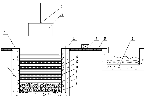
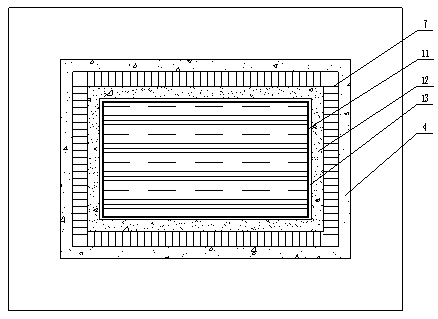
[0030] During specific implementation: if figure 1 and figure 2 As shown, a sludge treatment equipment includes a water-permeable layer assembly 1 and a suction device 2. The water-permeable layer assembly 1 encloses a sludge placement space with an upward opening, and a water accumulation space is provided outside the water-permeable layer assembly 1 in the circumferential direction. , the suction device 2 includes a water pump, the inlet end of the water pump is connected to the water accumulation space, and also includes a dynamic compaction device 3 arranged outside the mud storage space, and the dynamic compaction device 3 includes a The dynamic tamping hammer 31 above the storage space can move down along the depth direction of the silt storage space into the silt storage space for dynamic tamping.

[0031]In this technical solution, the silt is plac...


PUM


Abstract

The invention discloses a sludge treatment equipment which comprises a permeable layer component, wherein the permeable layer component defines a sludge placement space with an opening formed upwards; a water accumulation space is arranged on the outer side of the permeable layer component circumferentially and communicated and connected with an input port of a water pump in a suction device; the equipment further comprises a heavy-tamping device arranged on the outer side of the sludge placement space; the heavy-tamping device comprises a heavy-tamping hammer arranged above the sludge placement space; the heavy-tamping hammer can move downwards into the sludge placement space for heavy-tamping operation in a depth direction of the sludge placement space. The invention further discloses a sludge treatment method. According to the equipment and the method, a dehydration rate of sludge can be increased; a residual moisture content of the sludge after dehydration is lower; the dehydrated sludge can have better engineering properties.

Description

technical field [0001] The invention relates to the technical field of sludge treatment; in particular, it relates to a sludge treatment equipment and a method thereof. Background technique [0002] my country's rapid economic development has brought about a climax in the construction of water conservancy and port waterways. During the dredging and widening of various rivers and waterways, as well as in the construction and expansion of ports, a large amount of waste silt is inevitably produced. According to incomplete statistics, the discarded silt in my country reaches hundreds of millions of cubic meters every year: a considerable amount of silt is produced in coastal areas such as the East China Sea and the North Sea. The amount of silt produced by the dredging works of the river course is also considerable. At present, most of the inland dredged silt is discarded in landfill or low-lying areas, and some occupy the original fish ponds or cultivated fields. At present, th...

Claims


Application Information

Patent Timeline
Patent Type & Authority Patents(China)
IPC IPC(8): C02F11/121C02F11/14
CPCC02F11/121C02F11/14
Inventor 文桃应赛王升刘东升游强熊平赵成功舒云建
Owner YANGTZE NORMAL UNIVERSITY
Learn More