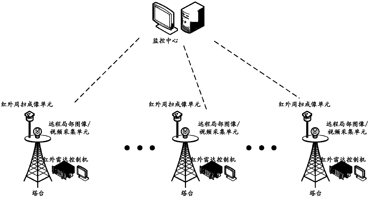
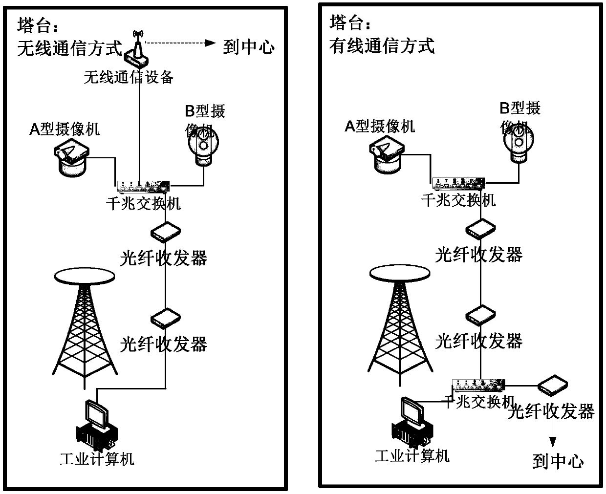
Wide-area, oil field infrared panoramic imaging radar reconnaissance command and control system

A command and control system and radar reconnaissance technology, which is applied to closed-circuit television systems, components of television systems, image communications, etc. The effect of safety production management ability

Active Publication Date: 2018-05-11
DAQING ANRUIDA TECH DEV CO LTD
View PDF10 Cites 0 Cited by
  • Summary
  • Abstract
  • Description
  • Claims
  • Application Information

AI Technical Summary

Problems solved by technology

[0002] There are a large number of facilities and equipment in the country's important material production and field operation areas such as oil fields. These facilities and equipment are distributed in many places and it is difficult to comprehensively monitor and protect them. It is difficult for the traditional single-point video surveillance system to cover every facility and equipment, and there are problems such as difficulty in construction and maintenance, and easy damage. This technical problem has always plagued the security department of the production company.
[0003] At present, the technical solution adopted by the oil field is to use ordinary guns or small-scale fast ball video surveillance equipment to monitor some operating areas that require key care at fixed points. This traditional video surveillance system generally installs a large number of front-end cameras to cover It needs to monitor the area, but it is difficult to deploy a large number of open areas in the field like the oil field, the cost is high, and it is easy to be damaged, and the later maintenance is difficult
These problems make it difficult for traditional video surveillance systems to adapt to the special requirements of oilfields
[0004] In summary, the existing technology has the following defects: it is difficult and costly to deploy a large number of single-well monitoring; the construction period of single-well monitoring is long, and the equipment model is difficult to unify; Monitoring field near-field placement, easy to damage; etc.

Method used


Image

  • Wide-area, oil field infrared panoramic imaging radar reconnaissance command and control system
  • Wide-area, oil field infrared panoramic imaging radar reconnaissance command and control system
  • Wide-area, oil field infrared panoramic imaging radar reconnaissance command and control system

Examples


Embodiment Construction

[0027] Exemplary embodiments of the present invention will be described below with reference to the accompanying drawings. In the interest of clarity and conciseness, not all features of an actual implementation are described in this specification. It should be understood, however, that in developing any such practical embodiment, many implementation-specific decisions must be made in order to achieve the developer's specific goals, such as meeting those constraints related to the system and business, and those Restrictions may vary from implementation to implementation. Moreover, it should also be understood that development work, while potentially complex and time-consuming, would at least be a routine undertaking for those skilled in the art having the benefit of this disclosure.

[0028]Here, it should also be noted that, in order to avoid obscuring the present invention due to unnecessary details, only the device structure and / or processing steps closely related to the s...


PUM


Abstract

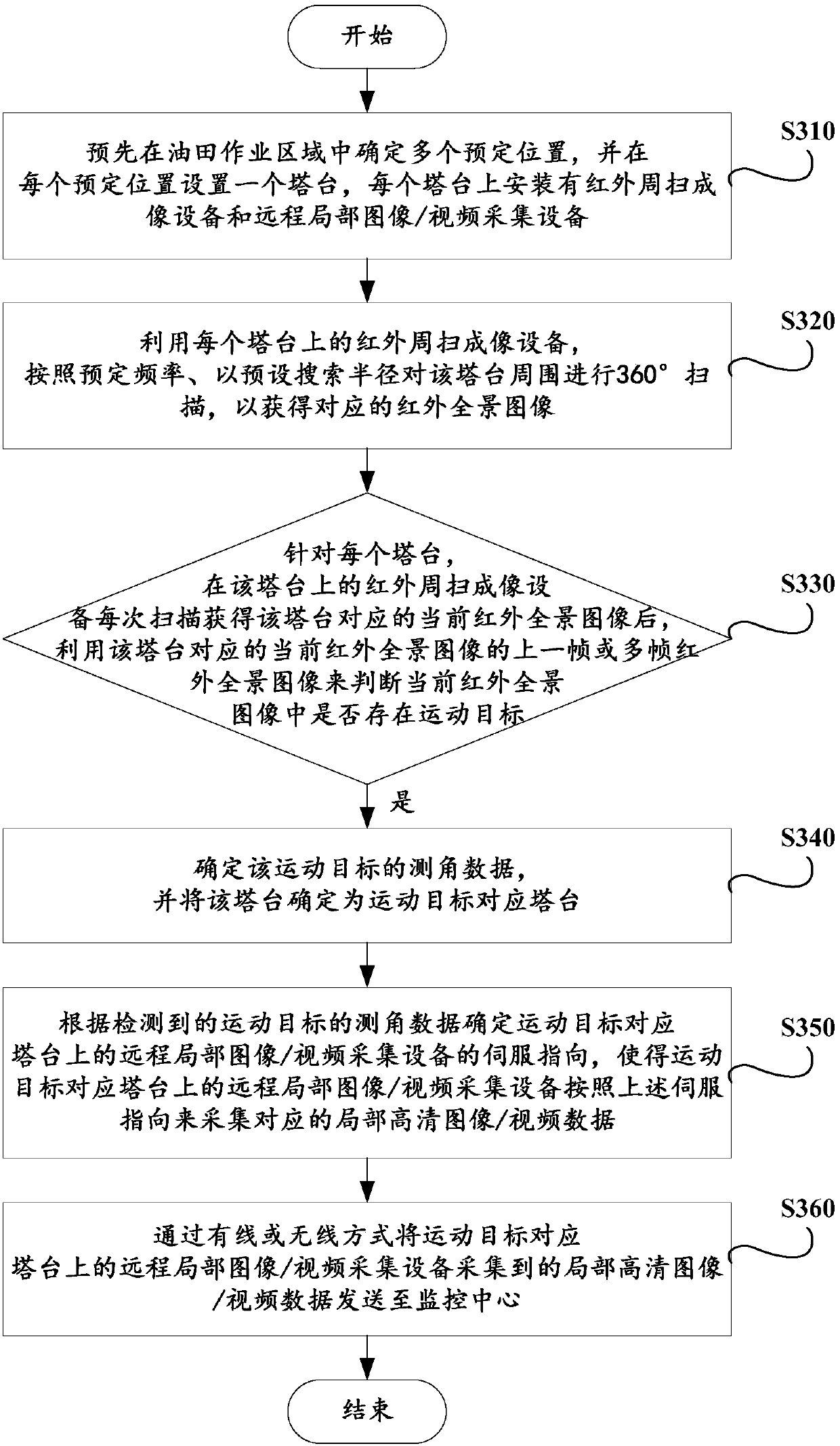
The invention provides a wide-area, oilfield infrared panorama imaging radar reconnaissance command and control system, which includes one or more towers and monitoring centers arranged at predetermined positions in the oilfield operation area. Each tower is equipped with: an infrared scan imaging unit, which scans horizontally 360° around the tower to obtain an infrared panoramic image; a moving target detection unit, which determines whether there is a moving target in the current infrared panoramic image, and determines it when there is a moving target Angle measurement data; the remote partial image / video acquisition unit determines the servo pointing of the remote partial image / video acquisition unit according to the angle measurement data to collect local high-definition image / video data; the sending unit transmits the remote partial image / video through wired or wireless The local high-definition image / video data collected by the collection unit is sent to the monitoring center. The above-mentioned technology of the present invention can be used for day and night monitoring of oil fields, has high monitoring and alarm accuracy, and has the advantages of low false alarm, low false alarm, highly simplified engineering and the like.

Description

technical field [0001] The invention relates to the field of oilfield safety management, in particular to a wide-area, oilfield infrared panoramic imaging radar reconnaissance command and control system. Background technique [0002] There are a large number of facilities and equipment in the country's important material production and field operation areas such as oil fields. These facilities and equipment are distributed in many places and it is difficult to comprehensively monitor and protect them. It is found that the traditional single-point video surveillance system is difficult to cover every facility and equipment, and there are problems such as difficulty in construction and maintenance, and easy damage. This technical problem has always plagued the security department of the production company. [0003] At present, the technical solution adopted by the oil field is to use ordinary guns or small-scale fast ball video surveillance equipment to monitor some operating ...

Claims


Application Information

Patent Timeline
Patent Type & Authority Patents(China)
IPC IPC(8): H04N7/18H04N5/262H04N5/14G08B13/196
CPCG08B13/19602H04N5/144H04N5/2624H04N7/188
Inventor 赵叶辰邹本泉马丽丽李明迪崔日华
Owner DAQING ANRUIDA TECH DEV CO LTD
Why Eureka
Try Eureka