A frequency-tunable sound wave generator
A technology of sound wave generation and jet cavity, which is applied in combustion product treatment, combustion method, lighting and heating equipment, etc., can solve problems such as mutual interference, inability to change the output frequency, and inability of sonic sootblowers to work, and achieve method implementation. Simple, simple process and compact system structure
- Summary
- Abstract
- Description
- Claims
- Application Information
AI Technical Summary
Problems solved by technology
Method used
Image
Examples
Embodiment 1
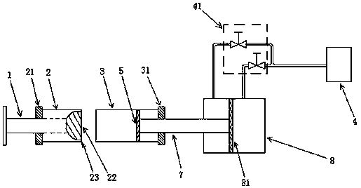
[0042] Such as figure 1 , is a schematic diagram of the structure of the frequency-tunable sound wave generating device provided in this embodiment, including a high-pressure air conduit 1, a jet chamber 2, a resonance chamber 3 and an air source 4; one end of the jet chamber 2 is provided with a jet chamber sealing end cover 21, and the other end A jet nozzle core 22 is provided, and there is a gap between the jet nozzle core 22 and the inner wall of the jet chamber 2 to form a jet nozzle 23; the high-pressure air conduit 1 passes through the sealing end cover 21 of the jet chamber and enters the interior of the jet chamber 2 and is connected to the jet nozzle core 22 The high-pressure air duct 1 inside the jet chamber 2 is provided with a through hole; one end of the resonance chamber 3 is open, and the other end is provided with a resonance chamber sealing end cover 31; Ensure that the gas ejected from the jet nozzle 23 enters the resonance chamber 3; inside the resonance c...
Embodiment 2
[0046] This embodiment is another improvement on the basis of Embodiment 1, such as figure 2 As shown, the slide plate 5 is connected with a reciprocating rod 7, and the reciprocating rod 7 passes through the sealed end cover 31 of the resonance cavity and then enters the cylinder 8 and is connected with the reciprocating plate 81 that can reciprocate along the axial direction of the cylinder 8; The source 4 is connected, and the valve 41 is arranged on the air pipe and controls the reciprocating plate 81 to perform reciprocating motion by controlling inflation and deflation.
[0047] In this embodiment, high-pressure air is passed into the high-pressure air conduit 1, and the high-pressure air enters the jet cavity 2 through the through hole on the high-pressure air conduit 1 inside the jet cavity 2, and the high-pressure air is compressed in the jet nozzle 5 after being collected in the jet cavity 2. After pressurization, it is sprayed into the resonance chamber 3, and the ...
Embodiment 3
[0049] This embodiment is a further improvement on the basis of Embodiment 1, as image 3 As shown, the trachea is provided with a first pressure transmitter 91 for detecting the size of the air pressure chamber 6, so that the generation of high-intensity sound waves can be controlled online; one end of the resonance chamber 3 is connected to the jet chamber 2 through a connecting piece, The integration and stabilization of the device is further realized. The jet nozzle core 22 is in the shape of a hemisphere, and the spherical surface of the hemisphere faces the inside of the jet cavity 2, so that the high-pressure air is uniformly discharged through the jet nozzle 23, which is easier to control and the resonance cavity 3 There is a limit device for limiting the sliding position of the slide plate 5 inside, which makes it easier to control the frequency of occurrence.
PUM
 Abstract
Description
Claims
Application Information
 - R&D
- Intellectual Property
- Life Sciences
- Materials
- Tech Scout
- Unparalleled Data Quality
- Higher Quality Content
- 60% Fewer Hallucinations
Browse by: Latest US Patents, China's latest patents, Technical Efficacy Thesaurus, Application Domain, Technology Topic, Popular Technical Reports.
© 2025 PatSnap. All rights reserved.Legal|Privacy policy|Modern Slavery Act Transparency Statement|Sitemap|About US| Contact US: help@patsnap.com


