
Pull and / or push rod

A technology of pull rods and push rods, which is applied in belts/chains/gears, transmission devices, manufacturing tools, etc., and can solve problems such as threaded hollow rod skew and system blockage

Inactive Publication Date: 2016-08-31
ROHM CO LTD
View PDF1 Cites 3 Cited by
  • Summary
  • Abstract
  • Description
  • Claims
  • Application Information

AI Technical Summary

Problems solved by technology

These threaded connections have the disadvantage that the outer threaded hollow rod is often skewed (verkanten) due to the large prevailing play
Here, the combination of a small thread overlap and a large prevailing gap in the overall structure can lead to undesired blocking of the system (blockade)

Method used


Image

  • Pull and / or push rod
  • Pull and / or push rod
  • Pull and / or push rod

Examples


Embodiment Construction

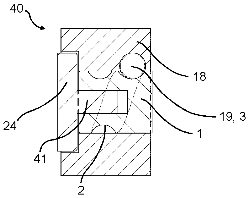
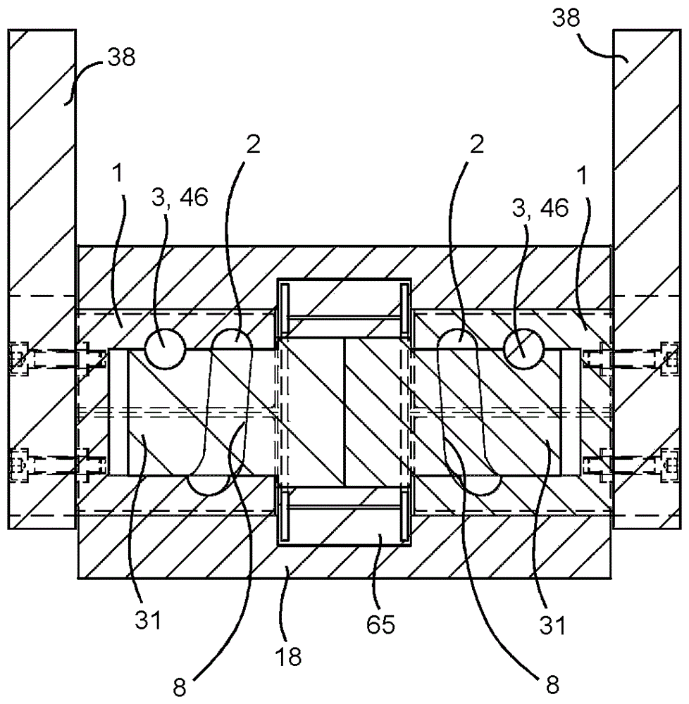
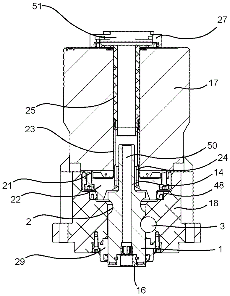
[0056] exist Figures 1a to 1e A draw rod and / or push rod 1 is shown in , which is displaceable along the rod longitudinal axis. The pull and / or push rod has a control curve 2 for guiding the control element 3 , which comprises an at least partially helical helix with one or more pitch sections 4 , 5 , 6 , 7 Section 8.

[0057] Furthermore, the control curve 2 comprises at least one free-running section 9 , 10 which is connected to the helical section 8 , extends substantially radially relative to the longitudinal axis of the rod, and is preferably arc-shaped. In the exemplary embodiment, exactly two free-travel sections 9 , 10 are provided, wherein the first free-travel section 9 is arranged at the first end of the spiral section 8 and wherein the second free-travel section 10 is arranged at a second end of the spiral section 8 opposite the first end. Preferably, the free-running sections 9 , 10 of the tie rod and / or push rod 1 extend radially relative to the rod longitudin...


PUM


Abstract

The invention relates to a pull and / or push rod 1 which is adjustable along a rod longitudinal axis. The pull and / or push rod (1) comprise a control curve portion (2) for guiding a control element (3). The control element comprises a coil section which is at least partially spiral-shaped and comprises a spiral section (8) with one or more screw portions (4, 5, 6, 7).

Description

technical field [0001] The invention relates to a pull rod and / or a push rod. Such machine parts are frequently used in clamping and clamping technology for being able to perform axial movements, that is to say along the longitudinal axis, for switching between clamping and loosening configurations relative to clamping or holding device. Background technique [0002] It is known here to bring about an axial movement of the component by means of a threaded connection between threaded rods or threaded hollow rods. This is described, for example, in DE 10 2011 116 818 A1 for a release unit, in which the axial movement of the release lever is via a screw drive consisting of two trapezoidal threads clamped into each other (ineinandergreifend) to fulfill. These threaded connections have the disadvantage that the outer threaded hollow rod is often skewed due to the large prevailing play. The deflection is here also caused by the fact that, depending on the position of the threa...

Claims


Application Information

Patent Timeline
Patent Type & Authority Applications(China)
IPC IPC(8): F16H25/24B23B31/26B23B31/28
CPCB23B31/26B23B31/28F16H25/24B23B31/16266B23B31/261F16H25/186B23B2231/50B23B2260/128B25J15/0273
Inventor S.坎普特
Owner ROHM CO LTD
Learn More