
Automatic tidying machine

A strip material and automatic technology, applied in the direction of feeding device, positioning device, storage device, etc., can solve the problem that the machine cannot realize automatic feeding and discharging, and consumes a lot of manpower, and achieves novel structure, simple feeding and guarantee. The effect of accurate positioning

Inactive Publication Date: 2016-06-15
TIANJIN FUDONG CAN MAKING
View PDF0 Cites 3 Cited by
  • Summary
  • Abstract
  • Description
  • Claims
  • Application Information

AI Technical Summary

Problems solved by technology

At present, although there are a variety of can end production equipment on the market, in the production process of can end, the machine cannot automatically load and discharge materials, and must be manually loaded and discharged, which consumes a lot of manpower

Method used


Image

  • Automatic tidying machine
  • Automatic tidying machine
  • Automatic tidying machine

Examples


Embodiment

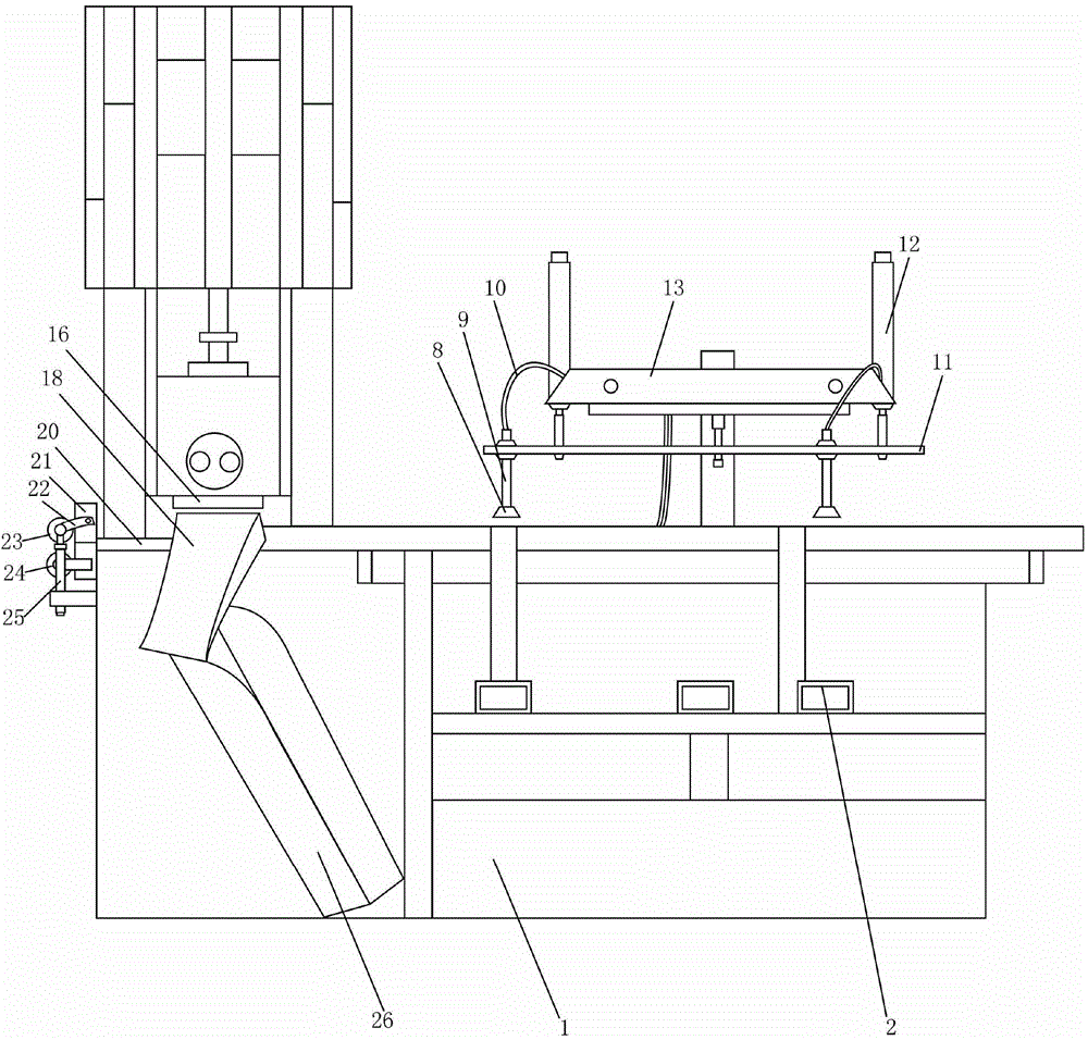
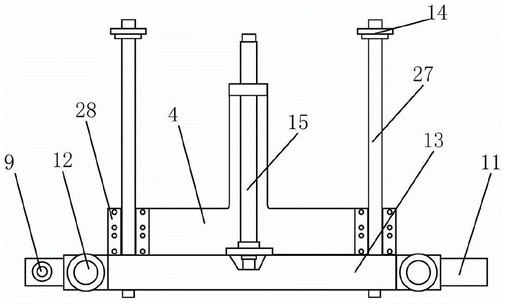
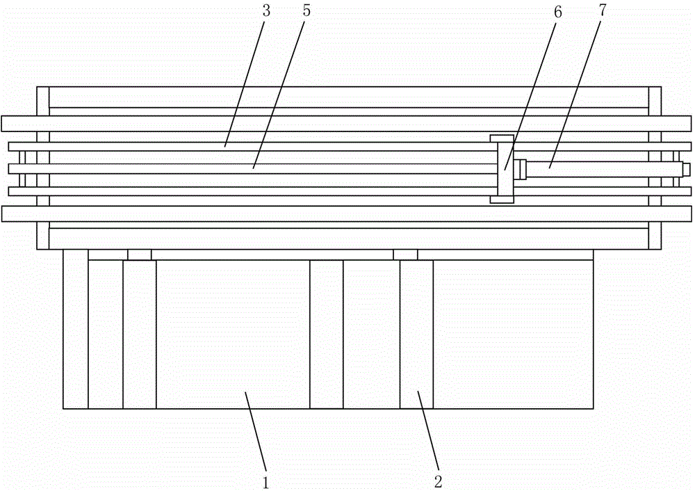
[0031] Such as Figure 1-5 As shown, an automatic strip machine includes a frame 1, a tank cover bracket 2, a screw nut slide rail 3, a fixed frame push plate 4, a lead screw 5, a lead screw nut 6, a lead screw nut cylinder 7, and a suction cup 8. Air pipe 10, connecting piece fixing plate 11, connecting piece fixing plate cylinder 12, connecting piece fixing plate cylinder fixing frame 13, fixing frame pushing plate 4, fixing frame pushing cylinder 15, stamping upper mold 16, stamping lower mold 17, finished product Discharge guide cylinder 18, air blowing pipe 19, waste guide rail 20, movable discharge roller fixing plate 21, movable discharge roller connecting plate 22, movable discharge roller 23, fixed discharge roller 24, movable discharge roller cylinder 25, tank The cover bracket 2, the lead screw nut slide rail 3, and the fixing frame push plate 4 are installed on the frame 1, the lead screw nut slide rail 3 is located on one side of the tank cover bracket 2, and the ...


PUM


Abstract

The invention belongs to the field of tank manufacturing equipment, and particularly relates to an automatic tidying machine. The automatic tidying machine is characterized in that one end of a screw nut is connected with a screw, and the other end of the screw nut is connected with a screw nut cylinder; suction cups are connected with air pipes, and connecting part fixing plate cylinders are connected with a connecting part fixing plate; a fixing frame pushing cylinder is mounted on a fixing frame pushing plate and connected with a connecting part fixing plate cylinder fixing frame; the upper end of a finished product discharging guide barrel and an air blowing pipe are oppositely arranged at the two sides of a lower stamping die; a waste guide rail and a screw nut slide rail are mounted at the two sides of the lower stamping die correspondingly; movable discharging roller connecting plates are connected with movable discharging roller fixing plates, the two ends of a movable discharging roller are connected with the movable discharging roller connecting plates, and movable discharging roller cylinders are connected with the movable discharging roller connecting plates.

Description

technical field [0001] The invention belongs to the field of can making equipment, in particular to an automatic strip machine. Background technique [0002] At present, many food, chemical raw materials, coatings, adhesives and other products sold on the market use metal cans as containers. During metal can manufacturing, the lid and body are produced separately before being assembled together. In the production process of the can lid, the can lid must go through 3 or 4 stamping procedures before it can be formed. At present, although there are a variety of can end production equipment on the market, during the production process of can ends, the machine cannot automatically load and discharge materials, and must be manually loaded and discharged, which consumes a lot of manpower. Contents of the invention [0003] Aiming at the above technical problems, the present invention provides an automatic strip material machine which can automatically load and discharge materia...

Claims


Application Information

Patent Timeline
Patent Type & Authority Applications(China)
IPC IPC(8): B21D51/44B21D22/02B21D43/02B21D43/18B21D43/20B21D45/00
Inventor 刘天文
Owner TIANJIN FUDONG CAN MAKING
Learn More