
Optical element reflectivity measurement instrument

A technology of optical components and reflectivity, which is applied in the field of instrument science, can solve the problems of measuring the size of optical components, failing to meet accuracy requirements, and unable to meet the requirements of online measurement of reflectivity of optical components, etc., and achieve the effect of simple structure and easy realization

Inactive Publication Date: 2016-04-27
LASER FUSION RES CENT CHINA ACAD OF ENG PHYSICS
View PDF13 Cites 4 Cited by
  • Summary
  • Abstract
  • Description
  • Claims
  • Application Information

AI Technical Summary

Problems solved by technology

[0003] The existing method of measuring the reflectance of optical components generally uses a spectrophotometer to measure the light transmittance, and then converts it into a reflectance method, which cannot meet higher precision requirements. It is necessary to seek new measuring instruments and new measuring methods
At present, some spectrophotometers have an accessory device for measuring reflectivity, but this instrument also has its disadvantages, that is, it uses a photomultiplier tube as a detector, which can only be used in a dark environment, and the size of the measuring optical element is limited. Can not meet the requirements of online measurement of reflectivity of optical components

Method used


Image

  • Optical element reflectivity measurement instrument

Examples


Embodiment 1

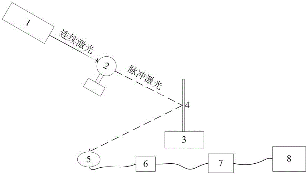
[0024] see figure 1 , the optical element reflectivity measuring instrument of the present invention comprises a laser 1, a light chopper 2, a sample loading platform 3, an optical standard sheet 4, a photodiode 5, a preamplifier 6, a lock-in amplifier 7 and a computer 8;

[0025] The laser light output by the laser 1 is modulated by the optical chopper 2 to become pulsed light, and the pulsed light is directly irradiated on the optical standard plate 4 or the optical element to be measured placed on the sample loading table 3, and the optical standard plate 4 or The reflected light reflected by the optical element to be tested is received by the photodiode 5 and converted into an electrical signal, and the electrical signal is respectively amplified by the preamplifier 6 and the lock-in amplifier 7 to output a DC voltage proportional to the intensity of the reflected light, and the DC voltage is obtained by the computer 8 receive and display.

[0026] The output laser of des...

Embodiment 2

[0031] Embodiment 2 is basically the same as Embodiment 1, the main difference being that an optical standard sheet 4 with a reflectance of 3.5% is replaced to measure the reflectance R of the optical element to be tested.


PUM

PropertyMeasurementUnit
reflectanceaaaaaaaaaa

Abstract

The invention provides an optical element reflectivity measurement instrument which is used for measuring the reflectivity of optical elements. The optical element reflectivity measurement instrument disclosed by the invention adopts a photodiode to collect reflecting light of an optical element or an optical standard sheet and transforms the reflecting light into an electric signal; after the electric signal is amplified by a pre-amplifier and a lock-in amplifier, a direct current voltage signal in direct proportion to signal light intensity is obtained. The instrument takes the direct current voltage signal obtained by measuring the reflecting light of the optical standard sheet as the benchmark, through comparing the direct current voltage signal obtained by measuring the reflecting light of the element to be measured with the benchmark, the reflectivity of the optical element to be measured is obtained. The optical element reflectivity measurement instrument disclosed by the invention is simple in structure, easy to realize, high in measurement accuracy, and capable of measuring the reflectivity of optical elements on line.

Description

technical field [0001] The invention belongs to the field of instrument science, and in particular relates to an optical element reflectivity measuring instrument. Background technique [0002] In many important application engineering and scientific research experiments in the country, such as high-power large-scale laser experiments, large-aperture optical components are required, and the quality of optical components is an important factor to ensure the success of the entire test, so it is necessary to focus on large-aperture optical components. High-precision measurement of performance reflectance. With the rapid development of laser technology, higher and higher requirements are put forward for the performance of laser coatings, among which the reflectivity of laser coatings is one of the most important parameters of coatings. Due to the higher accuracy requirements for some film reflectivity, for example: low reflectivity R<0.5%, high reflectivity R>99.7%. [0...

Claims


Application Information

Patent Timeline
Patent Type & Authority Applications(China)
IPC IPC(8): G01N21/55
CPCG01N21/55
Inventor 贾宝申吕海兵苗心向牛龙飞周国瑞刘昊李可欣
Owner LASER FUSION RES CENT CHINA ACAD OF ENG PHYSICS
Learn More