An electronic boundary device, an unmanned aerial system, and an unmanned aerial vehicle monitoring method
A technology of unmanned aerial vehicle and boundary system, applied in the field of monitoring of unmanned aerial vehicle flight area, can solve the problems that cannot be completed, the positioning information of unmanned aerial vehicle cannot be transmitted to the boundary monitoring function of the ground control system in time, and the signal is weakened, etc., to achieve Avoid the effect of disconnection
- Summary
- Abstract
- Description
- Claims
- Application Information
AI Technical Summary
Problems solved by technology
Method used
Image
Examples
Embodiment 1
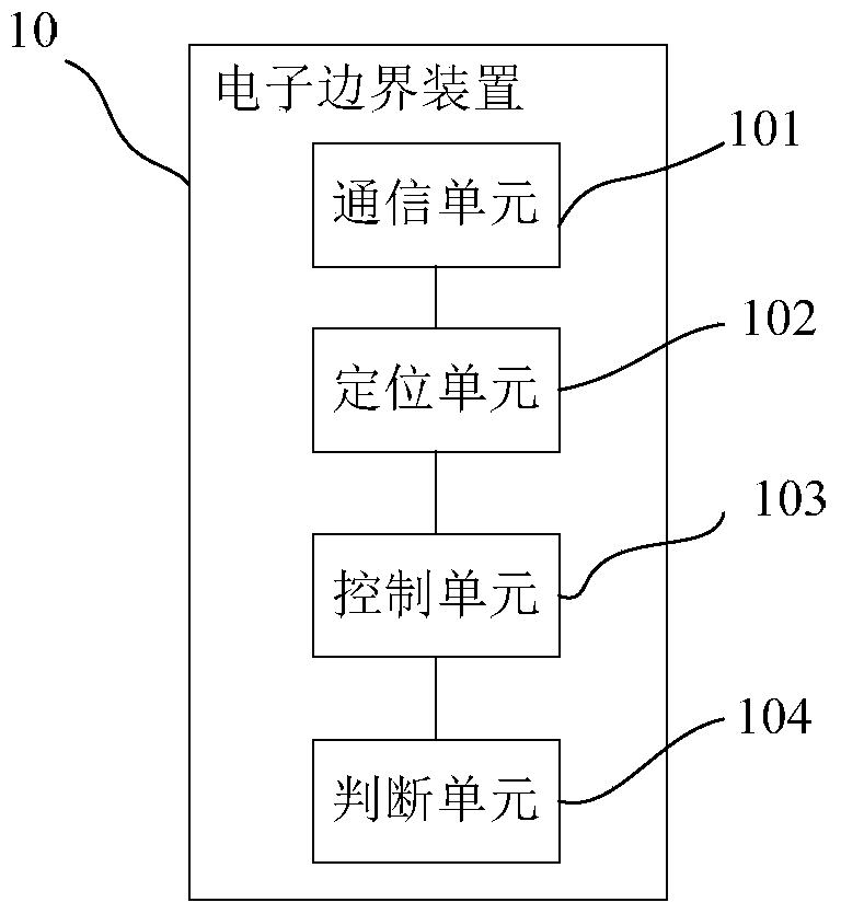
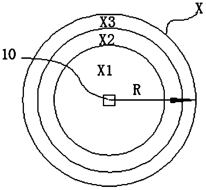
[0042] Figure 1a It is a schematic diagram of the basic composition of the electronic boundary system disclosed in this embodiment. Such as Figure 1a As shown, the electronic boundary system includes an electronic boundary device 10, one or more unmanned aerial vehicles 30, and a ground control system 20, and the above-mentioned electronic boundary device 10 is set independently of the above-mentioned unmanned aerial vehicle 30 or the ground control system 20. In other words, the above-mentioned electronic boundary device 10 can be moved to any position according to specific needs, and the above-mentioned electronic boundary device can be placed at a predetermined position to determine the above-mentioned flight area. In addition, in this embodiment, the flying area of the UAV 30 is determined based on the location information of the electronic border device 10 . Among them, such as Figure 1a As shown, the above-mentioned electronic boundary device 10 , the above-mentione...
Embodiment 2
[0069] The difference between this embodiment and Embodiment 1 is that in this embodiment, the electronic border system includes multiple electronic border devices 10 . That is to say, in this embodiment, a plurality of electronic boundary devices 10 are arranged on the flight route preset by the unmanned aerial vehicle 30. In this way, when the flight area is set with the position of the electronic boundary device 10 as the boundary, how many The area formed around each electronic boundary device 10 constitutes the flight area of the unmanned aerial vehicle 30, that is, the intersection of each flight area set with the position of each electronic boundary device 10 as the boundary constitutes the flight area of the unmanned aerial vehicle 30. Flight area; and when the flight area is set with the position of the electronic boundary device 10 as the center, the union of each flight area set with the position of each electronic boundary device 10 as the center constitutes the...
Embodiment 3
[0077] The difference between this embodiment and Embodiment 1 or Embodiment 2 is that in this embodiment, in order to enable the electronic boundary device to have a specific monitoring range, preferably, the above-mentioned electronic boundary device 10 also includes a pre-stored monitoring range information The storage unit and a verification unit for identifying and verifying the identity information of the unmanned aerial vehicle 30 and judging whether it belongs to the above-mentioned monitoring range information. Specifically, the above monitoring range information may be related information of one or more unmanned aerial vehicles that need to be monitored.
[0078] Figure 5 It is the flight monitoring method of using the electronic boundary device to monitor the flight of the unmanned aerial vehicle in this embodiment. Specifically, as Figure 5 As shown, at least one electronic boundary device 10 as mentioned above is placed at a preset position, and the flight are...
PUM
 Abstract
Description
Claims
Application Information
 - R&D Engineer
- R&D Manager
- IP Professional
- Industry Leading Data Capabilities
- Powerful AI technology
- Patent DNA Extraction
Browse by: Latest US Patents, China's latest patents, Technical Efficacy Thesaurus, Application Domain, Technology Topic, Popular Technical Reports.
© 2024 PatSnap. All rights reserved.Legal|Privacy policy|Modern Slavery Act Transparency Statement|Sitemap|About US| Contact US: help@patsnap.com


