
Light emitting diode (LED) lamp bead and LED light emitting module and LED street lamp with same

A technology of LED lamp beads and light-emitting modules, applied in the light source, electric light source, point light source, etc., can solve the problems of low utilization rate of light source and poor lighting effect, avoiding structural interference, convenient processing and assembly, and good glare. control effect

Active Publication Date: 2015-06-03
SHENZHEN BANG BELL ELECTRONICS
View PDF4 Cites 3 Cited by
  • Summary
  • Abstract
  • Description
  • Claims
  • Application Information

AI Technical Summary

Problems solved by technology

[0007] In order to overcome the technical problems of poor lighting effect and low light source utilization rate in the existing LED secondary optical treatment, the present invention provides an LED lamp bead with reasonable light pattern distribution, simple structure, wide irradiation range and high light source utilization rate and adopting The LED lighting module of the LED lamp bead and the LED street lamp

Method used


Image

  • Light emitting diode (LED) lamp bead and LED light emitting module and LED street lamp with same
  • Light emitting diode (LED) lamp bead and LED light emitting module and LED street lamp with same
  • Light emitting diode (LED) lamp bead and LED light emitting module and LED street lamp with same

Examples


Embodiment Construction

[0036] In order to make the purpose, technical solutions and advantages of the present invention more clear, the present invention will be further described in detail below in conjunction with the accompanying drawings and implementation examples. It should be understood that the specific embodiments described here are only used to explain the present invention, not to limit the present invention.

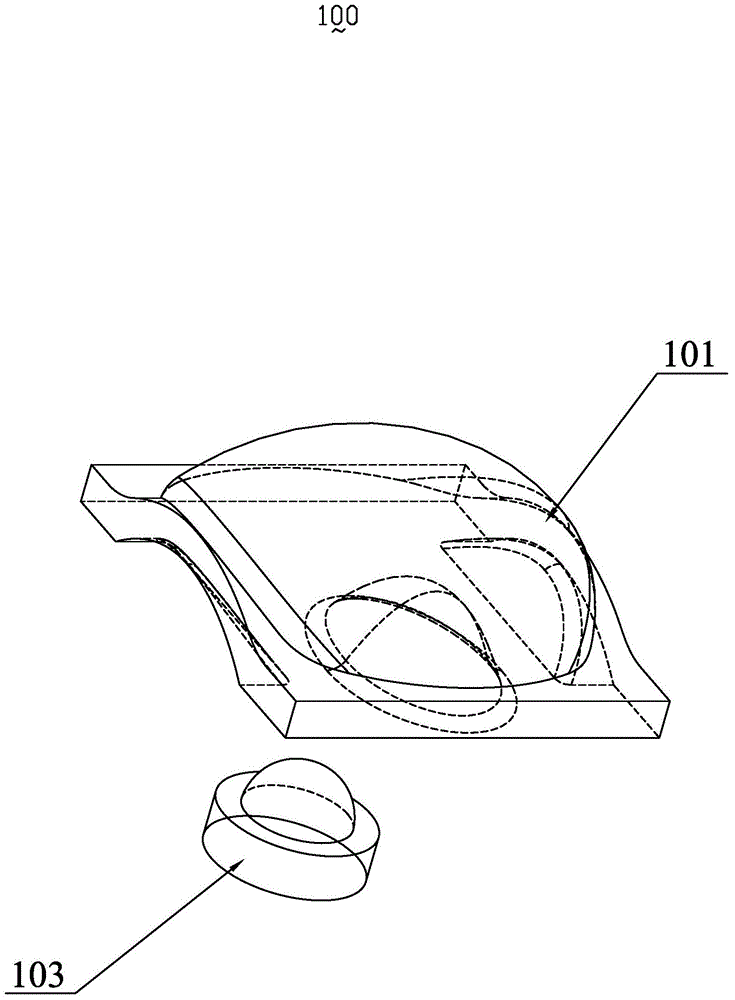
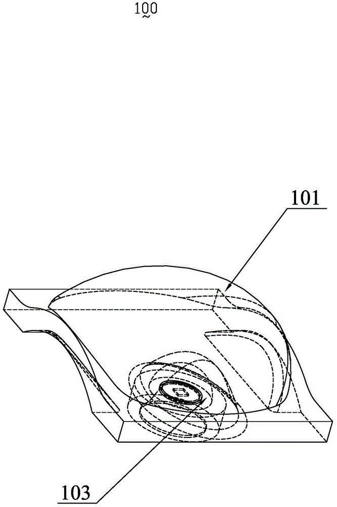
[0037] see figure 1 and figure 2 The LED lamp bead 100 of the present invention includes a lens 101 and an LED light source 103. The LED light source 103 is located inside the lens 101. When the LED light source 103 emits light, the light enters the lens 101 for secondary light distribution and then emits in a specific direction. The LED light source 103 mostly uses LED chips as light emitting elements, and its overall shape is a symmetrical structure.

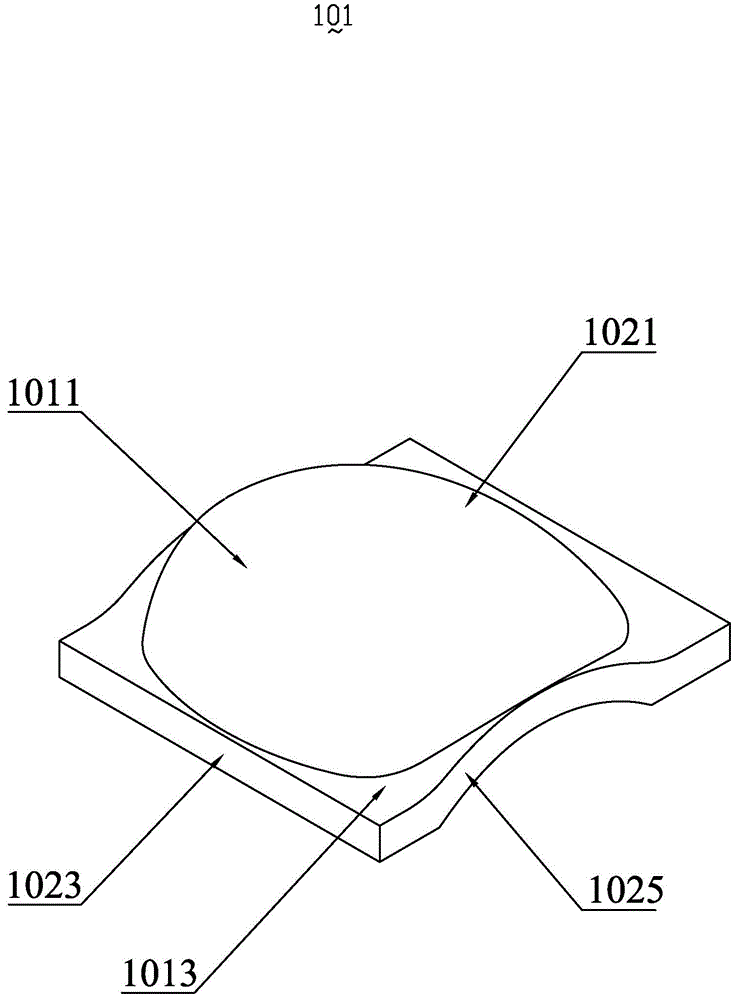
[0038] see image 3 and Figure 4, the upper part of the lens 101 is a curved surface 1011 , and the lower part is a horizon...


PUM


Abstract

The invention relates to a light emitting diode (LED) lamp bead for illumination. The LED lamp bead comprises an LED light source and a lens, the lens performs optical processing on light that is emitted by the LED light source, the lens is provided with an in-light surface and an out-light surface, the in-light surface is provided with an in-light surface optical center axis, the out-light surface is provided with an out-light surface optical center axis, the LED light source is provided with an LED light source optical center axis, lengths of optical paths from the LED light source to the in-light surface are unequal in terms of light rays that are symmetrically emitted from two sides of the LED light source optical center axis, lengths of optical paths from the in-light surface to the out-light surface are unequal in terms of the light rays that are symmetrically emitted from the two sides, and when all light rays that are symmetrically uniformly emitted from the two sides of the LED light source optical center axis are emitted on the out-light surface, the light ray density of one side of the LED light source optical center axis is larger than that of the other side of the LED light source optical center axis. The invention further provides an LED light emitting module and an LED street lamp with the LED lamp bead. The LED lamp bead and the LED light emitting module and the LED street lamp with the same have the advantages that the light patterns are reasonably distributed, the structure is simple, the illuminating range is wide, and the light source utilization rate is high.

Description

【Technical field】 [0001] The invention relates to an LED lamp bead for lighting, in particular to an LED lamp bead for street lamps irradiated with polarized light, an LED light-emitting module and an LED street lamp using the LED lamp bead. 【Background technique】 [0002] In the traditional lighting technology, tungsten filament bulbs are mostly used. Due to the large power consumption and volume, low luminous efficiency and short life, they are increasingly unable to meet the needs of modern society. With the development of semiconductor technology, the application of LEDs with small power consumption and volume, high luminous efficiency and long life in lighting technology has attracted more and more attention. As a new generation of light source, LED's secondary optical design is particularly important, but the biggest problem encountered is that LED lamps are composed of multiple point light sources into a surface light source, which is different from traditional light ...

Claims


Application Information

Patent Timeline
IPC IPC(8): F21S8/00F21V5/04F21V23/00F21W131/103F21Y101/02
CPCF21S8/085F21V5/04F21V19/001F21V23/00F21W2131/103
Inventor 何琳李剑张海卫
Owner SHENZHEN BANG BELL ELECTRONICS
Learn More