
Image rendering method and device

An image rendering and image technology, applied in the field of image rendering, can solve the problems of unreachable rendering speed, poor occlusion and lighting effects, and three-dimensional rendering effects

Active Publication Date: 2015-01-07
GUANGZHOU BOGUAN TELECOMM TECH LTD
View PDF3 Cites 54 Cited by
  • Summary
  • Abstract
  • Description
  • Claims
  • Application Information

AI Technical Summary

Problems solved by technology

[0005] However, if you use the first solution and continue to use pure 2D rendering, the occlusion and lighting effects are still worse than 3D rendering
However, if you use the second solution and switch to 3D rendering, you cannot achieve the same rendering speed as 2D rendering

Method used


Image

  • Image rendering method and device
  • Image rendering method and device
  • Image rendering method and device

Examples


Embodiment 1

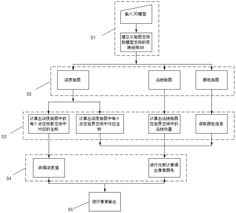
[0076] see figure 1 , which is the flow chart of Embodiment 1 of the 2.5D rendering method of the present invention. The 2.5D image rendering method of the present invention comprises the following steps:

[0077] S1: Establish a transformation matrix M from texture space to model space t , and its inverse matrix M t -1 ;

[0078] S2: Pass the 3D model through the transformation matrix M t -1 Transform from model space to texture space to generate depth map, normal map and color map respectively;

[0079] S3: Calculate the coordinates corresponding to each point in the depth map in the projection space and the corresponding coordinates in the world space, calculate the normal vector of each point in the normal map in the world space, and read the color information of the color map ;

[0080] S4: Obtain the depth value according to the coordinates of the depth map in the projection space; combine the coordinates of the points in the depth map in the world space, the nor...

Embodiment 2

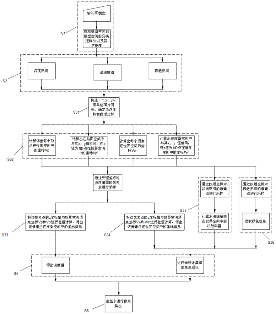
[0123] see image 3 , which is a flowchart of Embodiment 2 of the 2.5D rendering method of the present invention. The 2.5D image rendering method of the present invention comprises the following steps:

[0124] S1: Establish a transformation matrix M from texture space to model space t and its inverse matrix M t -1 ;

[0125] S2: Pass the 3D model through the transformation matrix M t -1 Transform from model space to texture space to generate depth map, normal map and color map respectively;

[0126] S3: Calculate the coordinates corresponding to each point in the depth map in the projection space and the corresponding coordinates in the world space, calculate the normal vector of each point in the normal map in the world space, and read the color information of the color map ;

[0127] S4: Obtain the depth value according to the coordinates of the depth map in the projection space; combine the coordinates of the points in the depth map in the world space, the normal v...


PUM


Abstract

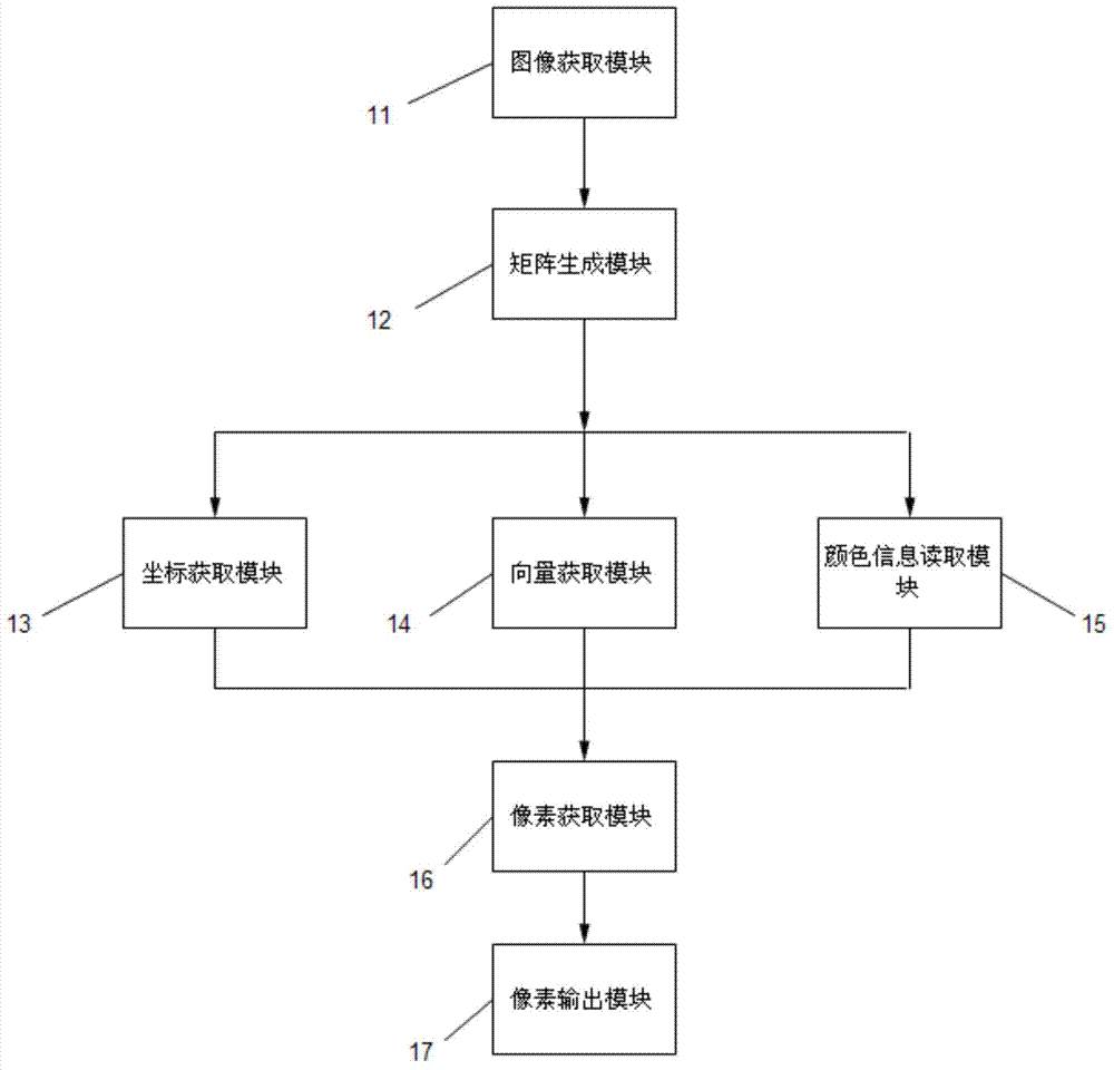
The invention relates to an image rendering method. The image rendering method includes the following steps that a depth map, a normal map and a color map of an image needing to be rendered are obtained; the coordinates and the depth values in the projection space and the coordinates and the normal vectors in the world space of all points in the image needing to be rendered are obtained; according to the color map, color information of all the points in the image needing to be rendered is obtained; illumination calculation is carried out to obtain pixel colors of all the points in the image needing to be rendered; pixels are output to obtain the rendered image. The invention further relates to an image rendering device used for achieving the method. Compared with the prior art, the two-dimensional rendering speed and the three-dimensional rendering effect are combined to achieve the effects that 2D face pictures are adopted for displaying appearances of objects, and 3D shielding and lighting effects are adopted for scenes, and therefore the two-dimensional rendering speed and the three-dimensional rendering effect can be achieved.

Description

technical field [0001] The invention relates to an image rendering method, in particular to a 2.5D image rendering method. Background technique [0002] 2D raster rendering refers to the method of directly rendering raster images to images or screens. The occlusion relationship is relatively simple, and the effect that can be achieved by color two-dimensional grid rendering can be achieved by this method, and can have better effects, such as: complex occlusion relationship, real-time light and shadow effects, these effects are often only achieved by 3D rendering engines . [0003] Compared with 3D rendering, the display effect of 2D rendering in the game has certain defects. For example: in a 2D rendering game with an oblique 45-degree viewing angle, A and B are two objects with mutual occlusion relationship in the game scene. It can only show the simple occlusion effect of A in front of B or B in front of A, and it is difficult to show complex scenes of mutual occlusion. ...

Claims


Application Information

Patent Timeline
IPC IPC(8): G06T15/00G06T15/10
CPCG06T15/506
Inventor 黄巍
Owner GUANGZHOU BOGUAN TELECOMM TECH LTD
Learn More