
Grinding wheel angle dresser

A dresser and grinding wheel technology, which is applied in the field of grinding wheel angle dressing equipment for surface grinders, can solve the problems of unsuitable grinding wheel angle high-precision dressing, low grinding wheel angle dressing accuracy, and inconvenient distance adjustment, so as to achieve reasonable setting and easy disassembly and assembly , to avoid the effect of interference

Active Publication Date: 2014-12-10
KUNMING HUIDIAO MACHINERY
View PDF8 Cites 0 Cited by
  • Summary
  • Abstract
  • Description
  • Claims
  • Application Information

AI Technical Summary

Problems solved by technology

Due to the unreasonable mechanism setting of the existing grinding wheel angle dresser, there are gaps between the mechanisms of the angle dresser, resulting in low grinding wheel angle dressing accuracy
It is mainly reflected in the fact that the existing grinding wheel angle adjuster adopts a common sliding guide rail structure. In order to maintain the smoothness of sliding, the pre-tightening force between its components is low, resulting in a slight shaking between the sliding guide rail components.
At the same time, during the use of the existing grinding wheel angle dresser, it is very inconvenient to adjust the distance between the grinding head and the grinding wheel. To achieve a more accurate distance adjustment, repeated manual adjustments are required, which is not suitable for high grinding wheel angles. Precision trimming

Method used


Image

  • Grinding wheel angle dresser
  • Grinding wheel angle dresser
  • Grinding wheel angle dresser

Examples


Embodiment Construction

[0021] The following will clearly and completely describe the technical solutions in the embodiments of the present invention with reference to the accompanying drawings in the embodiments of the present invention. Obviously, the described embodiments are only some, not all, embodiments of the present invention. Based on the embodiments of the present invention, all other embodiments obtained by persons of ordinary skill in the art without making creative efforts belong to the protection scope of the present invention.

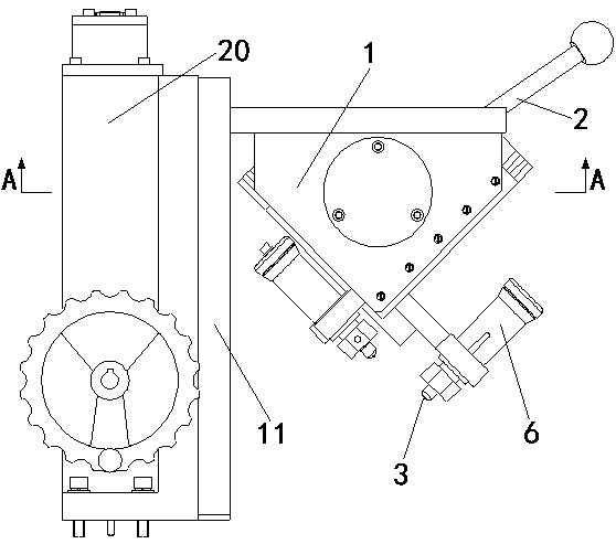
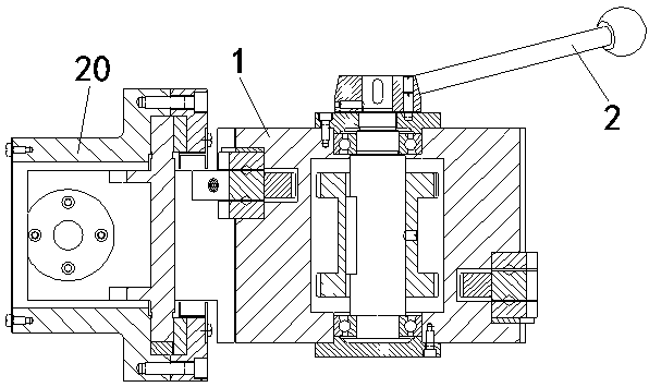
[0022] Figure 1-4 The shown grinding wheel angle dresser is installed on the grinding machine frame 20 and located above the grinding wheel during use. This grinding wheel angle dresser includes a dresser main body 1, a handle 2 and two guide rail mechanisms on which a diamond pen 3 is installed. The dressing The gear that meshes with the guide rail mechanism is arranged in the main body 1 of the device; the guide rail mechanism includes:

[0023] The rack g...


PUM


Abstract

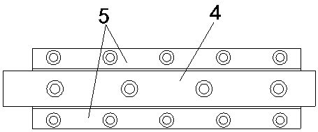
The invention discloses a grinding wheel angle dresser high in grinding wheel angle dressing precision. The grinding wheel angle dresser comprises a dresser body, a handle and two guide rail mechanisms, wherein diamond pens are arranged on the two guide rail mechanisms, and gears meshed with the guide rail mechanisms are arranged in the dresser body. Each guide rail mechanism comprises a rack guide rail and two guide strips, wherein the rack guide rail is fixedly connected with the corresponding diamond pen, one surface with a rack, of the rack guide rail is meshed with the corresponding gear in the dresser body, the rack guide rail moves when the handle is rotated, and the two guide strips are fixedly arranged on the dresser body, matched with the rack guide rail, positioned on the two sides of the rack guide rail respectively and connected with the rack guide rail in a matched mode through cross rollers. Compared with a conventional guide rail mechanism, the grinding wheel angle dresser can provide higher pretighenting force while normal sliding of the rack guide rails is not affected, it is ensured that clearance generating shaking between the guide rails is avoided basically, and machining precision of the diamond pens is improved effectively.

Description

technical field [0001] The invention relates to the technical field of grinding wheel angle dressing equipment for a surface grinder, in particular to a grinding wheel angle dressing device. Background technique [0002] At present, when the grinding wheel on the surface grinder is grinding, the angle of the grinding wheel needs to be trimmed frequently so that it can perform effective grinding. Due to the unreasonable setting of the mechanism of the existing grinding wheel angle dresser, there are gaps between the mechanisms of the angle dresser, resulting in low precision of the grinding wheel angle dressing. It is mainly manifested in that the existing grinding wheel angle adjuster adopts a common sliding guide rail structure. In order to maintain the smoothness of sliding, the pre-tightening force between its components is low, resulting in slight shaking between the sliding guide rail components. At the same time, during the use of the existing grinding wheel angle dre...

Claims


Application Information

Patent Timeline
IPC IPC(8): B24B53/06
CPCB24B53/06B24B53/12
Inventor 秦庆辉罗之光杨岗波杨惠民杨惠安
Owner KUNMING HUIDIAO MACHINERY
Learn More