
Improvements to Combustion Engines

A combustion engine, engine technology, applied in the direction of combustion engine, internal combustion piston engine, engine control, etc.

Inactive Publication Date: 2017-08-08
EHT PATENTS & LICENSING
View PDF14 Cites 0 Cited by
  • Summary
  • Abstract
  • Description
  • Claims
  • Application Information

AI Technical Summary

Problems solved by technology

[0011] Therefore, existing dual fuel systems have limitations such as requiring a minimum fraction of about 25% secondary fuel and / or requiring the ECU or primary fuel supply to be controlled or adaptable

Method used


Image

  • Improvements to Combustion Engines
  • Improvements to Combustion Engines
  • Improvements to Combustion Engines

Examples


Embodiment Construction

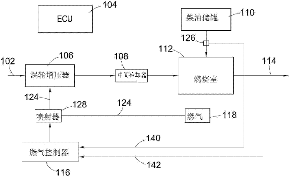
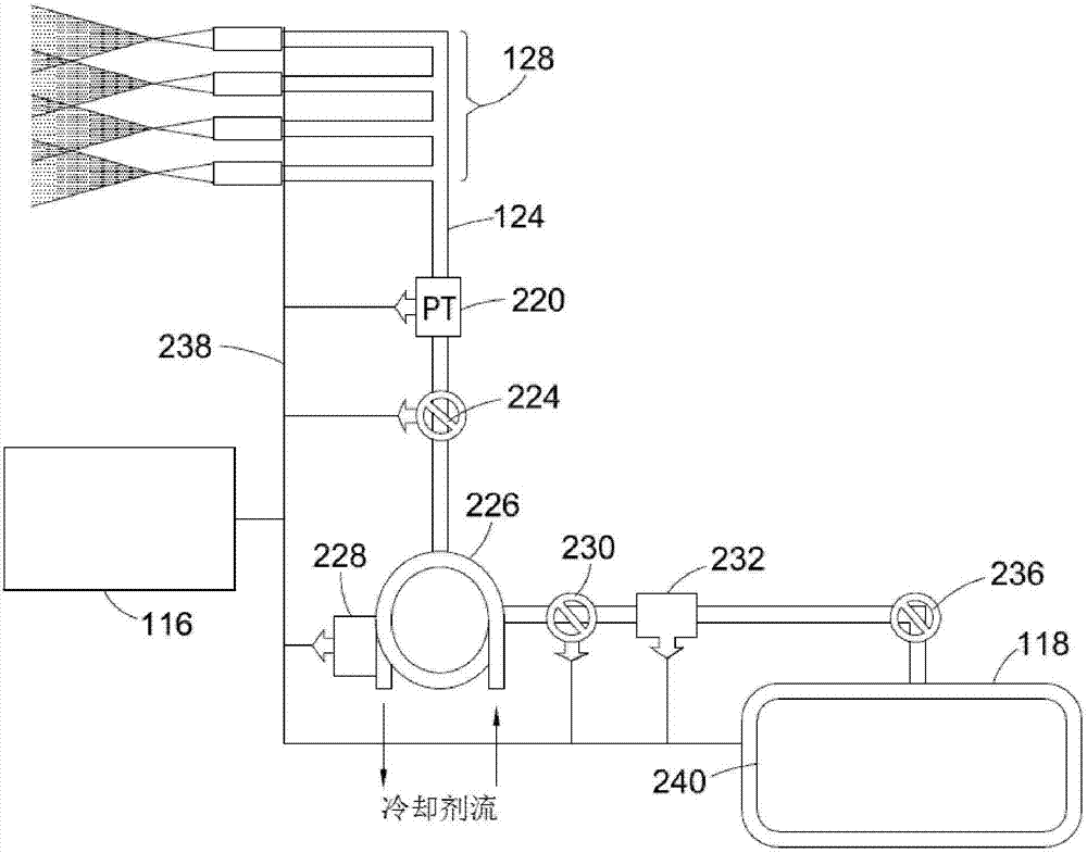
[0034] According to one embodiment, increasing the efficiency of an internal combustion engine is achieved without controlling and / or modifying the engine's ECU, main combustion chamber, or primary fuel supply. Instead, the amount of primary fuel (eg diesel) supplied is measured, and the controller can determine the optimal fraction of secondary fuel (eg gas) to be injected from a predetermined fuel map profile.

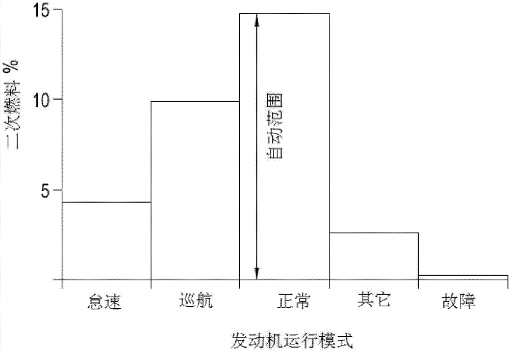
[0035] In one embodiment, the fuel mapping profile determines the fraction of secondary fuel to be injected as a function of primary fuel being injected. The fuel mapping profile is based on maintaining the engine in an enhanced co-combustion mode of operation throughout the engine's entire operating range. In other words, it is only necessary to inject exactly the correct amount of secondary fuel (gas) to maintain the engine in this enhanced combustion mode throughout its operating range.

[0036] According to one embodiment of operation, by optimizing the combusti...


PUM


Abstract

The present invention provides methods for improving the efficiency of combustion engines. The method includes measuring the amount of primary fuel supplied to the combustion engine. An operating state of the combustion engine is determined. A fuel mapping profile is selected based on the operating state of the combustion engine and an amount of secondary fuel to be injected as a fraction of a measured amount of primary fuel is determined from the fuel mapping profile.

Description

technical field [0001] The present invention relates to improvements in combustion engines and to combustion engines, particularly, but not exclusively, to improvements in the combustion efficiency of internal combustion engines. Background technique [0002] Engine operation using more than one fuel is known. Many of these systems attempt to reduce overall fuel costs by using less expensive secondary fuels instead of relatively more expensive primary fuels. This type of system can be retrofitted to existing engines or supplied as an integral part of the engine / vehicle by the manufacturer. There is a wide variety of systems produced for the automotive market, especially the light and heavy truck markets, where fuel costs constitute a significant cost to the operator. [0003] There are generally two types of systems that are typically used. [0004] The first type of system works by introducing a secondary fuel in addition to the primary fuel. The amount of primary fuel ...

Claims


Application Information

Patent Timeline
Patent Type & Authority Patents(China)
IPC IPC(8): F02D19/08F02D19/06F02D41/00
CPCF02D19/0628F02D19/0647F02D19/066F02D19/081F02D41/0025F02D41/3094F02D19/061Y02T10/30F02D19/0602
Inventor G·麦克马洪
Owner EHT PATENTS & LICENSING
Learn More