
A transformer riser lead wire clamping device

A clamping device, lead wire technology, applied in the direction of transformer/inductor coil/winding/connection, etc., can solve the problem of poor electrical strength and mechanical strength of laminated wood materials, insufficient insulation distance, and can not meet the noise level of converter transformers It can reduce the partial discharge, improve the heat dissipation effect, and avoid the phenomenon of air pockets.

Active Publication Date: 2017-03-29
SHANDONG DACHI ELECTRIC
View PDF4 Cites 0 Cited by
  • Summary
  • Abstract
  • Description
  • Claims
  • Application Information

AI Technical Summary

Problems solved by technology

Although some effective measures have been taken in the design stage of converter transformers, they still cannot meet the strict requirements of users on the noise level of converter transformers; After friendly negotiation, the DC transformer manufacturer finally decided to adopt the "box-in" noise reduction scheme, that is, put the transformer body in a box with good sound insulation effect
[0003]Due to the adoption of "box-in" noise reduction measures, the height of the transformer riser is much higher than that of the ordinary scheme, and the lead wires of the converter transformer terminals are passing through the When the riser seat is connected with the bushing line, if it is not fixed, because the length of the lead wire is long, it is easy to cause the lead wire to be eccentric, and the insulation distance of the lead wire is reduced on one side and increased on the other side, so that the insulation distance at the reduced place is not enough , causing a discharge to occur
The second is that when the converter transformer is running, under the action of mechanical vibration and electromagnetic force, the lead wire is easy to swing, which will eventually cause the discharge of the lead wire to the rising seat and damage the connection of the components connected to it.
During the application of this scheme, some problems have been exposed, such as: ① Since the limb plate is welded on the inner wall side of the raised seat, in order to meet the requirements of the insulation distance, the diameter of the raised seat needs to be large enough
②The laminated wood material used for the lead clamp is relatively thick, the transformer oil is not easy to penetrate, and it is not conducive to the heat dissipation of the lead here
③ The electrical strength and mechanical strength of laminated wood materials are poor

Method used


Image

  • A transformer riser lead wire clamping device
  • A transformer riser lead wire clamping device
  • A transformer riser lead wire clamping device

Examples


Embodiment Construction

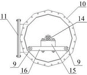
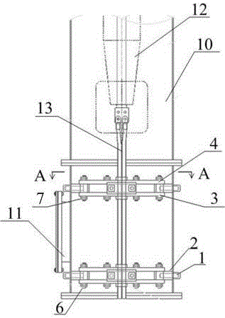
[0018] The drawings show a specific embodiment of the invention. The lead clamping device of the transformer elevated base of the present invention includes a laminated cardboard support frame 2 located inside the elevated base 10, a first laminated cardboard support 3 located below the laminated cardboard support frame 2, and a second laminated cardboard support 4 located above , And the laminated cardboard cover plate 5, there are 4 fixing holes 17 on the wall of the raised base 10, the fixing holes 17 are welded with round head nuts 1, and the laminated cardboard support frame 2 is passed through the screw 6 and the nut 7. The fixing hole 17 and the round head nut 1 are fixed inside the raised seat 10. The first laminated cardboard support 3, the laminated cardboard branch line 2 and the second laminated cardboard support 4 are fixed by the screw 6 and the nut 7. The laminated cardboard cover 5 is located at the center of the elevated base 10 and fixed on the first laminated...


PUM


Abstract

The invention relates to a clamping device for a transformer, in particular to a lead clamping device for an ascending flanged base of the transformer. The lead clamping device is characterized by comprising laminated paper board branch frames on the inner side of the ascending flanged base, first laminated paper board supports under the laminated paper board branch frames, second laminated paper board supports on the laminated paper board branch frames and laminated paper board cover boards. The wall of the ascending flanged base is provided with four fixing holes. Round-head nuts are welded outside the fixing holes. The laminated paper board branch frames are fixed to the interior of the ascending flanged base in the mode that screw rods and nuts penetrate through the fixing holes and the round-head nuts. The first laminated paper board supports, the laminated paper board branch frames and the second laminated paper board supports are fixed through the screw rods and the nuts. The laminated paper board cover boards are arranged in the center of the ascending flanged base and fixed to the first laminated paper board supports and the second laminated paper board supports.

Description

Technical field [0001] The invention relates to a clamping device for a transformer, in particular to a lead clamping device for a transformer riser. Background technique [0002] At this stage, with the development of high-voltage, large-capacity AC and DC transmission systems, the noise pollution of transformers has become more and more prominent, especially converter transformers for DC transmission, because they are not only subject to DC bias during operation, but also Subject to the influence of higher harmonics. Although some effective measures have been taken in the design stage of converter transformers, they still cannot meet the strict requirements of users on the noise level of converter transformers. Under such background conditions, some converter transformer users have joined the Power System Design Institute and The current transformer manufacturer, after friendly negotiation, finally decided to adopt the "box-in" noise reduction plan, that is, put the transforme...

Claims


Application Information

Patent Timeline
Patent Type & Authority Patents(China)
IPC IPC(8): H01F27/30H01F27/29
Inventor 董景义陈学民赵加旺
Owner SHANDONG DACHI ELECTRIC
Learn More