
Method for controlling electronic device and electronic device

An electronic device and electronic control technology, which is applied in the electronic field, can solve the problems of slow adjustment of the monitoring camera angle, etc., and achieve the effect of enhancing real-time monitoring, fast adjustment, and solving the effect of slow adjustment angle

Inactive Publication Date: 2014-06-11
LENOVO (BEIJING) LTD
View PDF9 Cites 5 Cited by
  • Summary
  • Abstract
  • Description
  • Claims
  • Application Information

AI Technical Summary

Problems solved by technology

[0006] The invention provides a method for controlling an electronic device and the electronic device to solve the technical problem in the prior art that the adjustment angle of the monitoring camera is slow

Method used


Image

  • Method for controlling electronic device and electronic device
  • Method for controlling electronic device and electronic device
  • Method for controlling electronic device and electronic device

Examples


Embodiment Construction

[0030] The embodiment of the present application solves the technical problem in the prior art that the angle adjustment of the monitoring camera is slow by providing a method for controlling an electronic device and the electronic device.

[0031] The technical solution in the embodiment of the present application is to solve the above-mentioned problem that the surveillance camera adjusts the angle slowly, and the general idea is as follows:

[0032] The position of the information collection device is adjusted directly according to the state of the controllable magnetic unit. Since the switching of the controllable magnetic unit is linked with the position adjustment of the information collection device, there is no motor corresponding control in the prior art. The response time of the command, therefore, effectively solves the problem of the slow adjustment angle of the monitoring camera in the prior art, realizes the rapid adjustment of the position of the information coll...

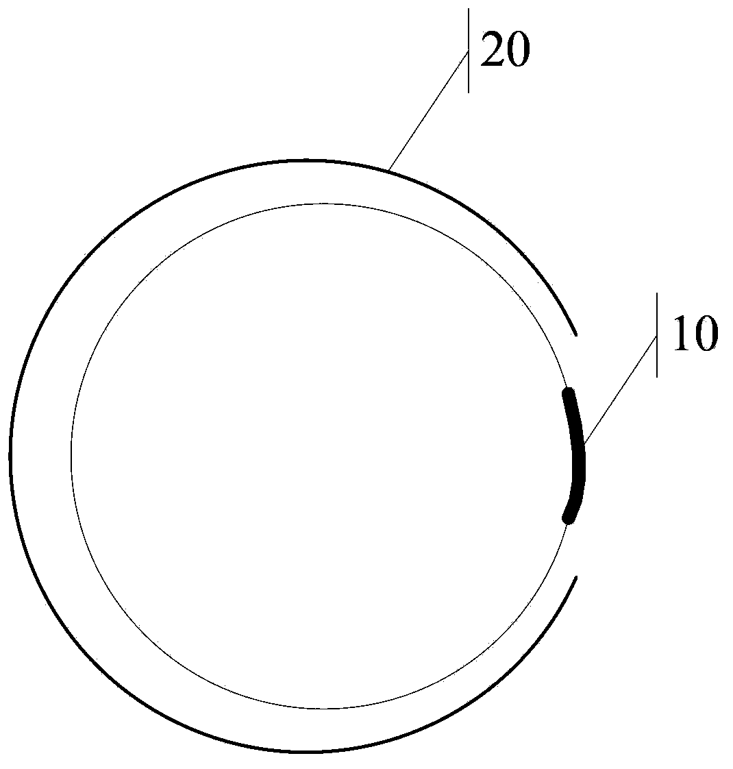
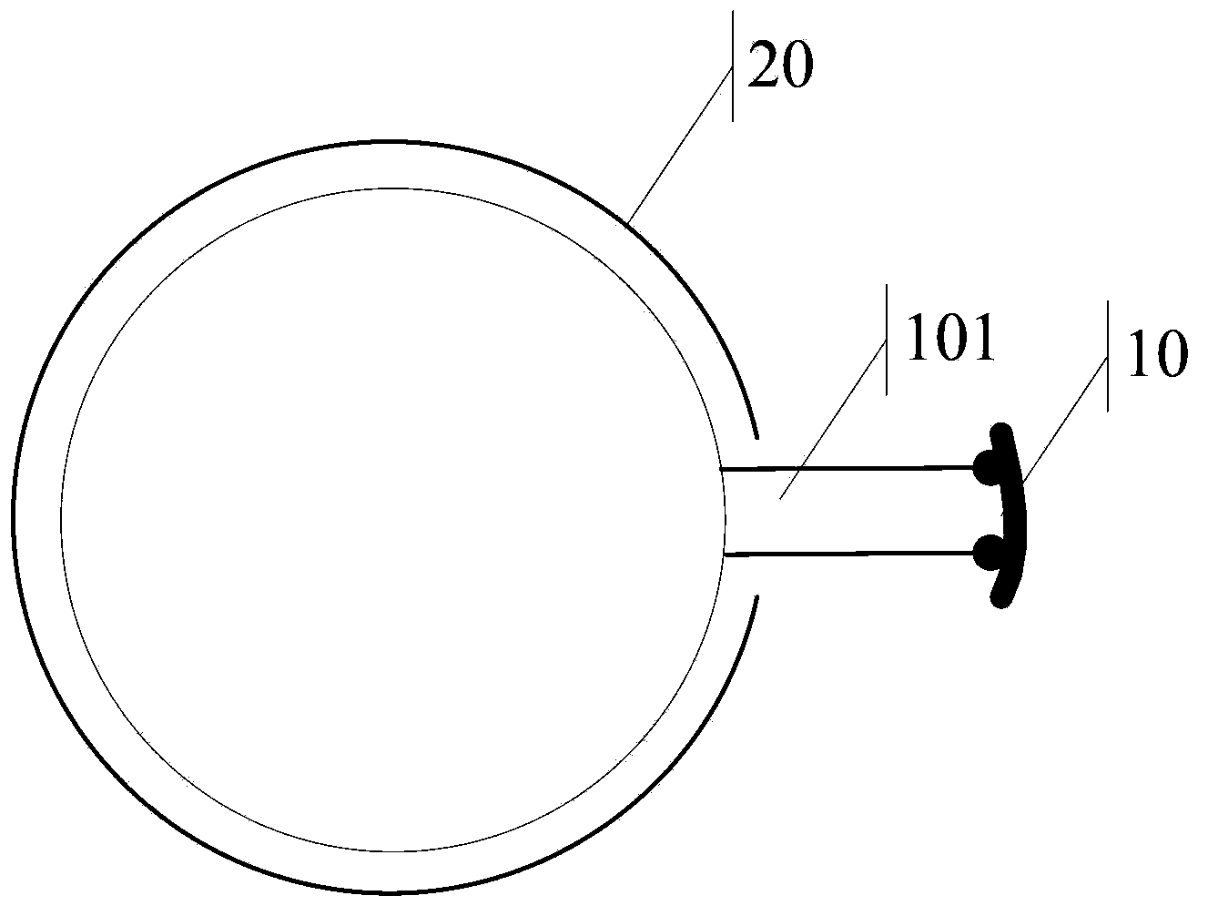
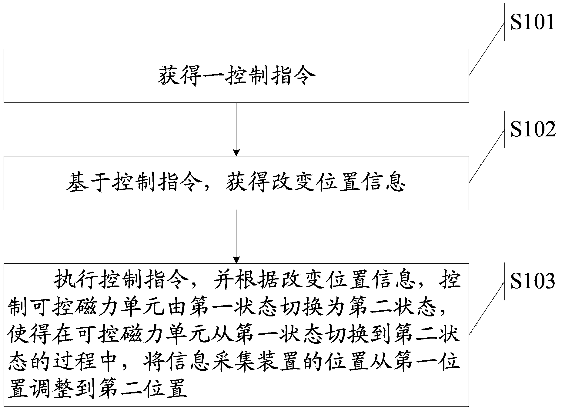

PUM


Abstract

The invention discloses a method for controlling an electronic device and an electronic device. The method is applied to the electronic device, and the electronic device comprises an information collecting device and a controllable magnetic force unit. The method includes the steps that a control instruction is obtained; based on the control instruction, position change information is obtained; the control instruction is executed, the controllable magnetic force unit is switched to be in a second state from a first state according to the position change information, and in the switching process, the position of the information collecting device is adjusted to be at a second position from a first position.

Description

technical field [0001] The invention relates to the field of electronic technology, in particular to a method for controlling electronic equipment and the electronic equipment. Background technique [0002] With the development of science and technology, security monitoring systems are widely used in people's lives, for example, installing surveillance cameras in public places, or setting infrared alarms on fences. [0003] At present, when a target object such as a thief or a suspicious person enters the shooting area, the target object may move out of the shooting range due to the movement of the target object. It can always appear near the central position of the monitoring screen. In the prior art, the surveillance camera is all fixed on the pan-tilt, and at least one motor is arranged on the pan-tilt, and the surveillance system rotates the pan-tilt by controlling the operation of the motor, so that the shooting angle of the surveillance camera changes. [0004] In th...

Claims


Application Information

Patent Timeline
Patent Type & Authority Applications(China)
IPC IPC(8): G05D3/12
Inventor 阳光
Owner LENOVO (BEIJING) LTD
Learn More