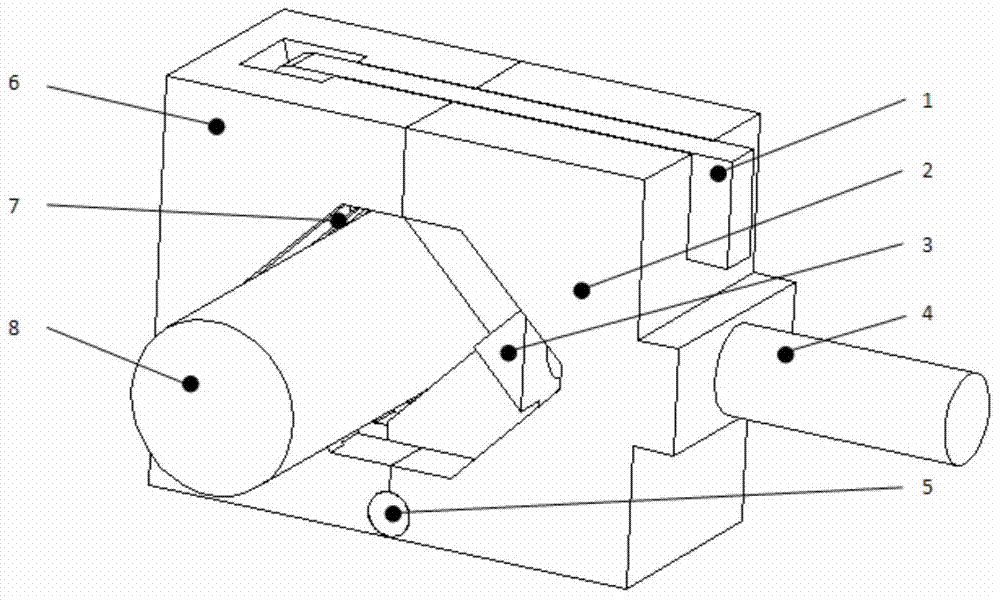
A shaft holder
A clamper and shaft clamping technology, which is applied in the direction of clamping and friction clamping detachable fasteners, supports, etc., can solve the problems of narrow application range, inability to realize clamping and locking, etc., and achieve a large clamping range , good centering effect, and the effect of increasing the diameter range
- Summary
- Abstract
- Description
- Claims
- Application Information
AI Technical Summary
Problems solved by technology
Method used
Image
Examples
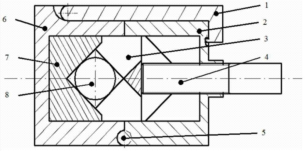
Embodiment 1
[0043] like figure 1 As shown, a shaft holder includes a V-shaped block, a housing and a V-shaped block pressing screw 4; the V-shaped block includes a left fixed V-shaped block 7 and a right movable V-shaped block 3, the housing It includes a left casing 6 and a right casing 2; the shaft holder also includes a left and right casing locking buckle 1; the left fixed V-shaped block 7 and the right movable V-shaped block 3 are respectively wrapped by the casing; the The left fixed V-shaped block 7 is fixedly connected with the housing; the left fixed V-shaped block 7 and the right movable V-shaped block 3 are provided with cross-arranged meshing teeth on the opposite tooth openings, so that they can adapt to different The diameter range of the object to be clamped varies; the top of the casing is provided with a guide groove, the right movable V-shaped block 3 is higher than the left fixed V-shaped block 7, and its higher part is embedded in the guide groove on the top of the cas...
Embodiment 2
[0045] like figure 2 As shown, a shaft holder is similar to Embodiment 1, the difference is that the diameter of the clamped member 8 is determined by both the housing and the V-shaped block. When the V-shaped block is pressed against the screw 4 When moving to the rightmost end, the distance between the left fixed V-block 7 and the right movable V-block 3 is the largest, and the diameter of the clamped part 8 is the largest without touching the shell; when the V-block presses the screw 4 When pushed to the leftmost end, the left fixed V-shaped block 7 and the right movable V-shaped block 3 mesh with each other. If the volume allows, the two can be fully meshed until the gap between them is zero; the V-shaped block presses the screw 4 is connected with the right housing 2 through fine thread, and is in active contact with the right movable V-shaped block 3.
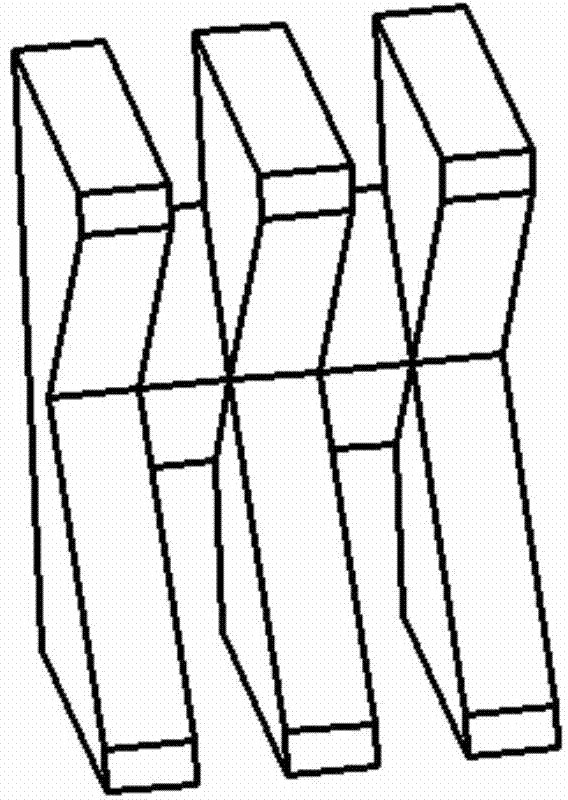
Embodiment 3
[0047] like Figure 3 to Figure 5 As shown, a shaft holder is similar to Embodiment 2, the difference is that the upper, lower and rear sides of the left fixed V-shaped block 7 are in contact with the interior of the left housing 6, which passes through the two middle A countersunk head bolt is fixed on the left housing 6, the bolt only plays a positioning role, and does not bear compressive force or tensile stress during the clamping process.
PUM
 Abstract
Description
Claims
Application Information
 - R&D Engineer
- R&D Manager
- IP Professional
- Industry Leading Data Capabilities
- Powerful AI technology
- Patent DNA Extraction
Browse by: Latest US Patents, China's latest patents, Technical Efficacy Thesaurus, Application Domain, Technology Topic, Popular Technical Reports.
© 2024 PatSnap. All rights reserved.Legal|Privacy policy|Modern Slavery Act Transparency Statement|Sitemap|About US| Contact US: help@patsnap.com


