
Piezoelectric vibrator, oscillator, electronic device, and radio-controlled timepiece

A technology of piezoelectric vibrator and piezoelectric vibrating piece, applied in piezoelectric/electrostrictive/magnetostrictive devices, manufacturing/assembly of piezoelectric/electrostrictive devices, circuits, etc., can solve the problem of low position accuracy, Decrease, undisclosed effective solutions and other issues, to achieve the effect of preventing the decline of electrical characteristics

Inactive Publication Date: 2013-09-18
SII CRYSTAL TECH
View PDF1 Cites 0 Cited by
  • Summary
  • Abstract
  • Description
  • Claims
  • Application Information

AI Technical Summary

Problems solved by technology

[0007] However, it has been found that in recent years, along with the miniaturization of the piezoelectric vibrator, the distance between the lead-out electrodes parallel to the vibrating arm portion and the vibrating arm portion tends to be narrowed. Hammer metal attached to detour electrode
If the flying weight metal adheres to the lead-out electrode, the lead-out electrode may be short-circuited or the electrical characteristics may be lowered
Furthermore, if the positional accuracy of the mounting position of the piezoelectric vibrating reed is low, there is a possibility that the laser beam will be directly irradiated to the lead-out electrode.
[0008] That is, in the prior art, since the flying weight metal is attached to the lead-out electrode or the laser beam is directly irradiated to the lead-out electrode, there is a possibility that the electrical characteristics of the lead-out electrode may decrease every time the frequency adjustment process is performed.
In addition, no effective solution has been disclosed so far for the problem newly discovered by the inventors of the present application.

Method used


Image

  • Piezoelectric vibrator, oscillator, electronic device, and radio-controlled timepiece
  • Piezoelectric vibrator, oscillator, electronic device, and radio-controlled timepiece
  • Piezoelectric vibrator, oscillator, electronic device, and radio-controlled timepiece

Examples


Embodiment Construction

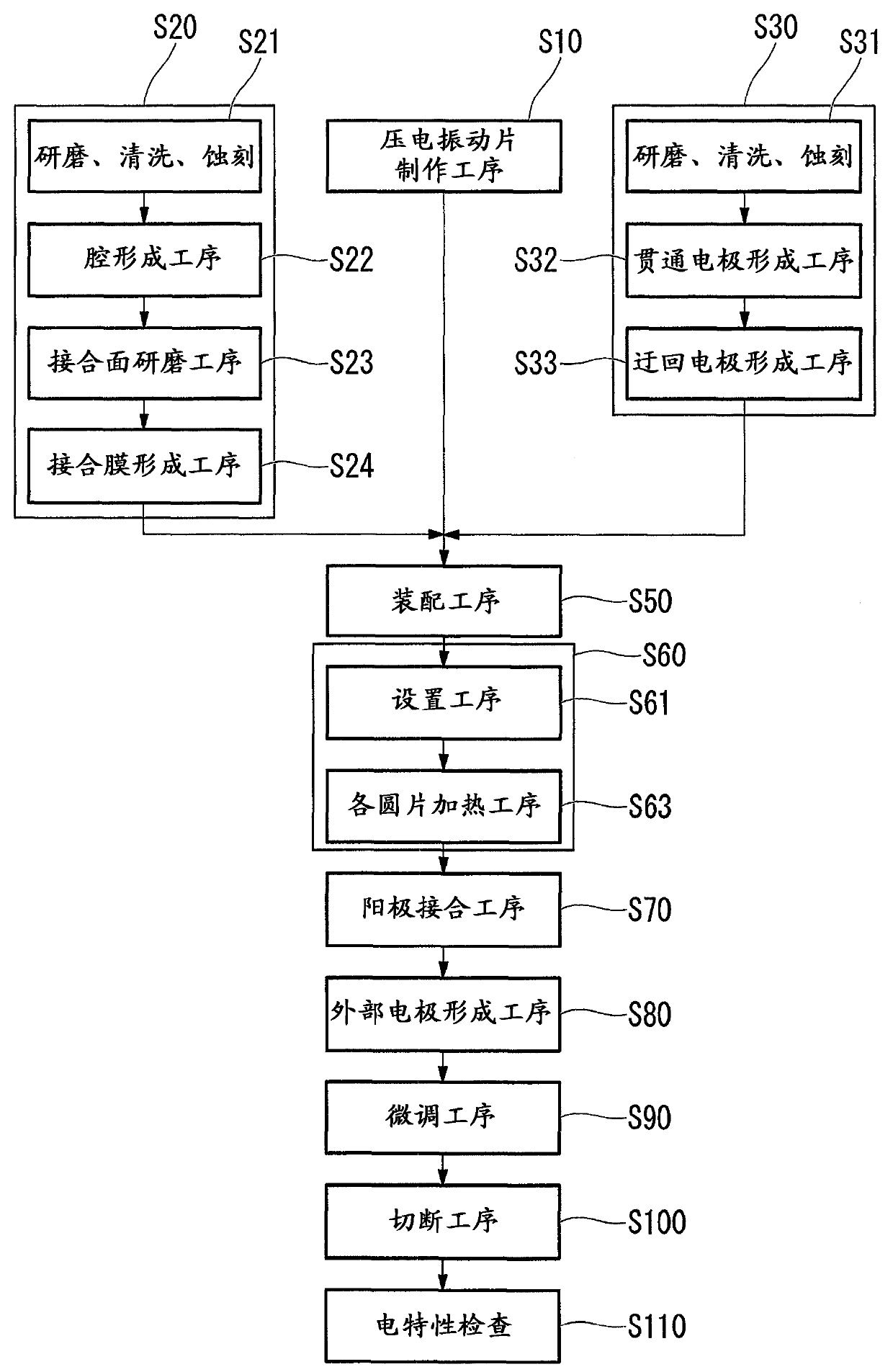
[0027] (Piezo Vibrator)

[0028] Hereinafter, a piezoelectric vibrator according to an embodiment of the present invention will be described with reference to the drawings.

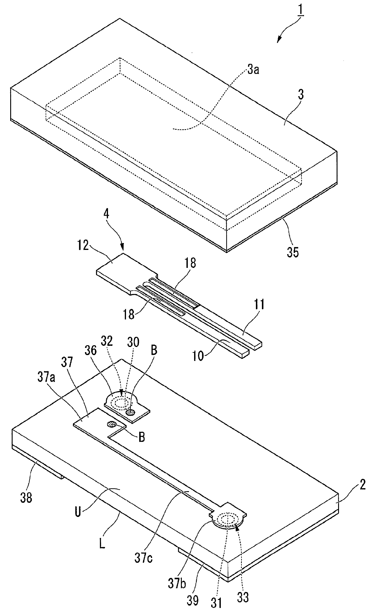
[0029] In addition, in the following description, the first substrate is used as a wafer for a base substrate and the second substrate is described as a wafer for a lid substrate. In addition, the bonding surface of the base substrate to the lid substrate is defined as an upper surface (inner surface) U, and the surface opposite to the surface is defined as a lower surface L.

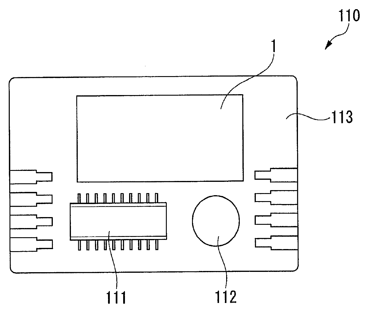
[0030] figure 1 It is a perspective view of the appearance of the piezoelectric vibrator.

[0031] figure 2 It is a diagram of the internal structure of the piezoelectric vibrator, and it is a plan view of the state where the lid substrate is removed.

[0032] image 3 yes figure 2 Sectional view at line A-A.

[0033] Figure 4 yes figure 1 An exploded perspective view of the piezoelectric vibrator shown.

[0034] In ad...


PUM


Abstract

Provided are a piezoelectric vibrator, an oscillator, an electronic device, and a radio-controlled timepiece capable of preventing lowering of an electrical characteristic of a routing electrode during the frequency adjustment with respect to a piezoelectric vibrator whose frequency can be adjusted by irradiating a laser beam onto a weight metal film formed on a distal end of a vibrating arm portion. In a piezoelectric vibrator (1), a routing electrode (37) is arranged in an offset manner toward one side with respect to a center line (C2) of a base substrate (2) in the lateral width direction, and a piezoelectric vibrating piece (4) is arranged in an offset manner toward a side opposite to the routing electrode (37) with respect to the center line (C2) of the base substrate (2) in the lateral direction.

Description

technical field [0001] The present invention relates to piezoelectric vibrators, oscillators, electronic equipment, and radio-controlled timepieces. Background technique [0002] For example, piezoelectric vibrators using quartz (crystal) as a time source, a timing source of control signals, a reference signal source, etc. as disclosed in Patent Document 1 are often used in mobile phones and portable information terminals. [0003] As such a piezoelectric vibrator, there is a piezoelectric vibrator in which a tuning-fork-type piezoelectric vibrating piece is hermetically sealed in a package in which a cavity is formed. The package has a structure in which one of a pair of glass substrates is superimposed on each other in a state where a concave portion is formed, and the two are directly bonded, whereby the concave portion functions as a cavity. In addition, the piezoelectric vibrating reed includes a pair of vibrating arm portions arranged in parallel to each other, and a ...

Claims


Application Information

Patent Timeline
Patent Type & Authority Applications(China)
IPC IPC(8): H03H9/10H01L41/053H10N30/87H10N30/06H10N30/88
CPCH03H9/1021H03H9/21H03H2003/026H03H9/1042Y10T29/42H10N30/87H10N30/06
Inventor 荒武洁
Owner SII CRYSTAL TECH
Learn More