
Pneumatic glue gripping device

A pneumatic and cylinder push rod technology, which is applied to conveyor objects, transportation and packaging, etc., can solve the problems of high labor intensity and low handling efficiency, and achieve the effect of reducing labor intensity, improving work efficiency and increasing friction coefficient.

Active Publication Date: 2013-06-12
万向新元科技股份有限公司
View PDF7 Cites 2 Cited by
  • Summary
  • Abstract
  • Description
  • Claims
  • Application Information

AI Technical Summary

Problems solved by technology

[0005] The purpose of the present invention is to propose a pneumatic rubber gripper, which solves the problems of low handling efficiency and high labor intensity of existing rubber raw materials

Method used


Image

  • Pneumatic glue gripping device
  • Pneumatic glue gripping device
  • Pneumatic glue gripping device

Examples


Embodiment 1

[0023] like Figure 1 to Figure 7 As shown, a specific embodiment of the present invention is given.

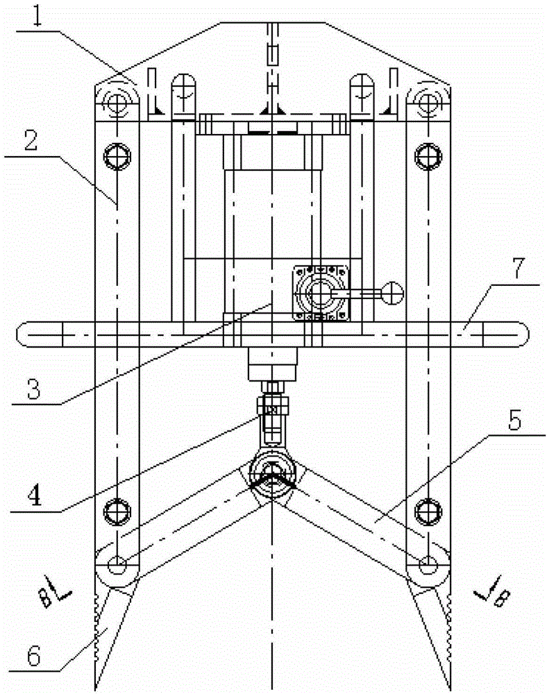
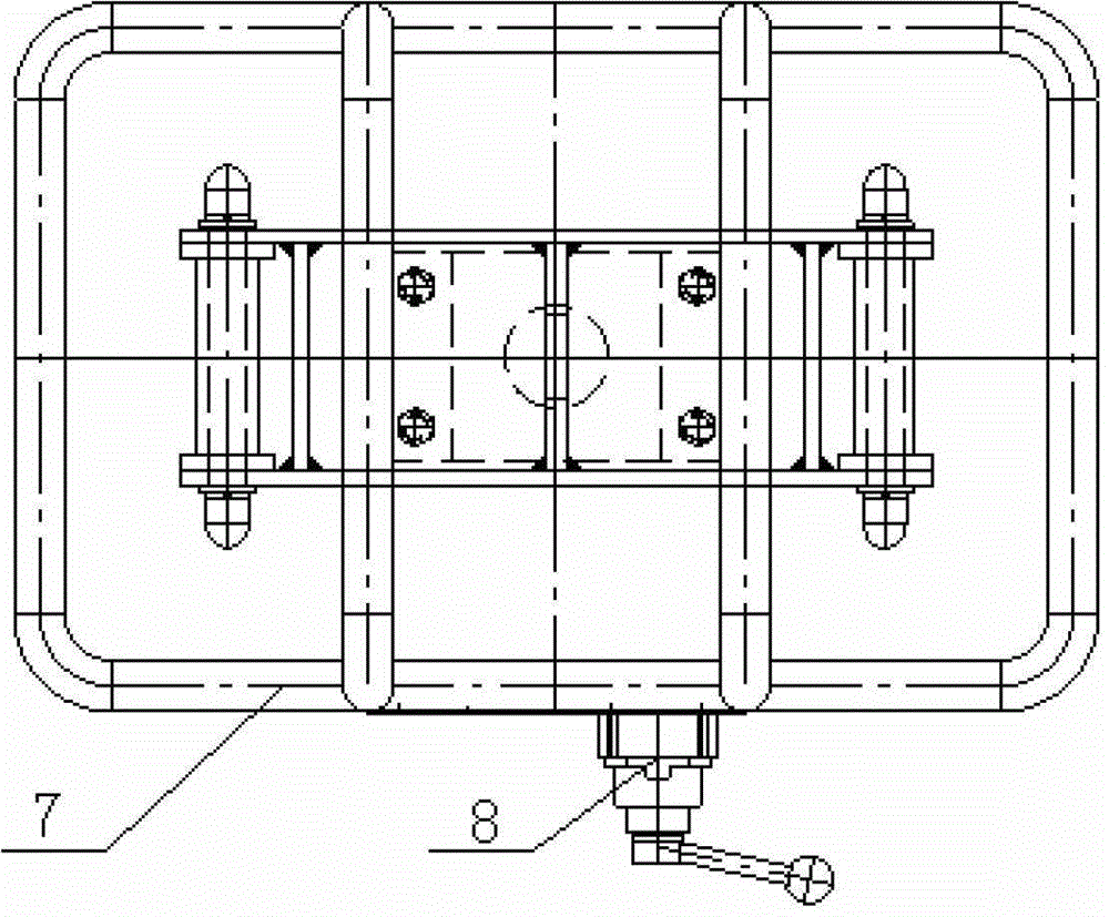
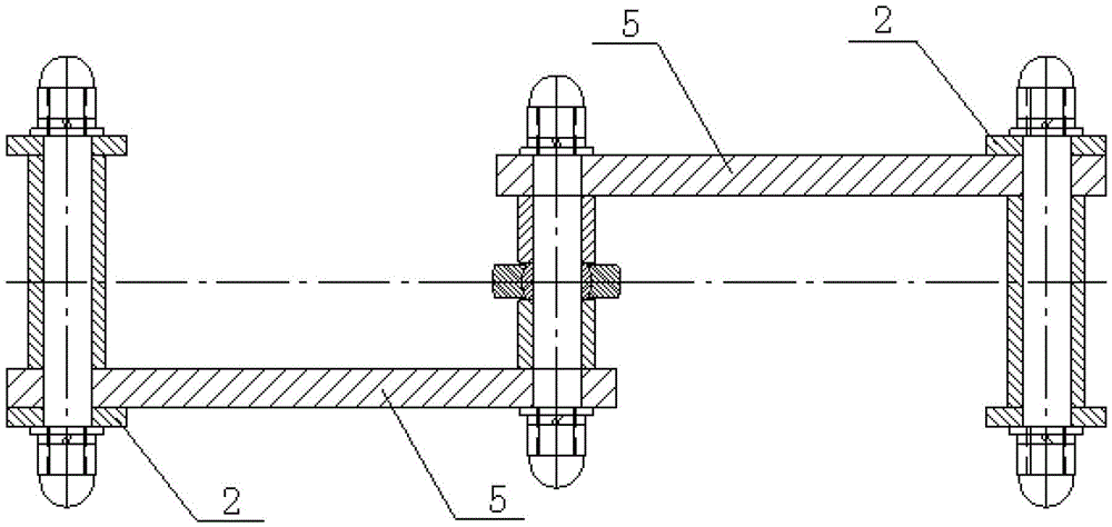
[0024] like figure 1 , figure 2 , image 3 Shown, a kind of pneumatic glue gripper, comprises the base 1 that is used to connect hoisting device and the driving device under the base 1, transmission mechanism and grasping device, and described driving device is the cylinder 3 that is installed under the base 1; Described includes the swing arm 2 that is symmetrically arranged at the lower end of the base 1 and the cylinder push rod at the lower end of the cylinder 3. The grabbing device is a pair of grabbing knives that are symmetrically arranged at the lower end of the swing arm 2, including a knife handle 5 and a knife head 6. The knife handle 5 and the cutter head 6 are of an integrated structure, and the two form an angle of 120 degrees. The upper ends of the two knife handles 5 are jointly hinged with the connecting rod at the lower end of the cylinder push rod, and ...

Embodiment 2

[0031] The handle of the grabbing knife and the cutter head form an integral crescent shape, the middle part of the grabbing knife is hinged with the lower end of the swing arm, and the upper ends of the handles of the two grabbing knives are jointly hinged with the connecting rod at the lower end of the cylinder push rod.

[0032] Others are the same as in Example 1.

[0033] The invention adopts the cylinder as the drive, and through the transmission of the connecting rod mechanism, it drives the grasping knives set opposite to grab the rubber material. The friction coefficient makes it more firm, fast and convenient to grab the rubber material, effectively reduces the labor intensity and improves the work efficiency.


PUM


Abstract

A pneumatic glue gripping device comprises a base used for being connected with a hoisting device as well as a driving device, a transmission mechanism and a gripping device, which are arranged under the base, wherein the driving device is an air cylinder mounted below the base; the transmission mechanism comprises a swing arm and an air cylinder push rod, which are arranged at the lower end of the base symmetrically; the gripping device is a pair of gripping knives arranged at the lower end of the swing arm symmetrically, and comprises knife holders and knife heads which are integrally formed; the upper ends of the two knife holders are jointly hinged with the lower end of the air cylinder push rod; the lower ends of the knife holders are hinged with the tail end of the swing arm; the knife points at the lower ends of the knife heads are acute angles; and the inner sides of the knife heads are ground into edges. In the pneumatic glue gripping device, the air cylinder is taken to drive, a link mechanism is used for driving, so as to drive the blades in the opposite directions to grip glue, so that not only the structure is simple, but also grooves are formed in the back surfaces of the blades to increase the friction coefficient between the knife back and the glue, which causes the glue gripping to be firmer, quicker and more convenient, reduces the labor intensity effectively, and improves the working efficiency.

Description

technical field [0001] The invention relates to a device for grabbing rubber material in a rubber mixing workshop in the rubber industry, in particular to a pneumatic rubber grabber. Background technique [0002] There are many kinds of tires and rubber products, and different products require different formulas and rubber mixing processes. Therefore, before the rubber material enters the internal mixer for mixing, the whole rubber material needs to be processed by cutting and weighing according to the proportioning requirements of the formula. [0003] In the rubber mixing workshop, the rubber materials are usually stacked near the rubber material cutting equipment, and they are tightly packed. The operating space for grabbing the rubber materials is only the upward side. The side of each piece of rubber material cannot be used due to the tight code. The operation mode of clamping the rubber material is used for grabbing. Usually, the geometric shape of the whole piece of...

Claims


Application Information

Patent Timeline
Patent Type & Authority Applications(China)
IPC IPC(8): B65G47/91
Inventor 朱业胜王际松王英斌陈洪昌
Owner 万向新元科技股份有限公司
Learn More