
Aviation building tray stopper driving device

A driving device and stopper technology, applied in the direction of conveyor control devices, transportation and packaging, conveyor objects, etc., can solve the problems of large size, slow response speed, time-consuming and other problems of mechanical driving devices, and achieve beautiful appearance , weight reduction, and simple structure

Inactive Publication Date: 2012-05-23
江苏海陵机械有限公司
View PDF4 Cites 0 Cited by
  • Summary
  • Abstract
  • Description
  • Claims
  • Application Information

AI Technical Summary

Problems solved by technology

At present, the drive mechanism for rising and falling through the pallet stopper in the aviation building adopts a mechanical drive device, and its disadvantages are: ①, poor quick response ability, the empty pallets are conveyed on the belt conveyor at a speed of 30 per minute, and the pallets are turning from one belt to the other. Other intersecting belts, according to the flow distribution to the stopper, the rising and falling time is only 0.7 seconds, and the response speed of the mechanical drive device is slow; ②, the durability is poor, and it is easy to be damaged when used. There are thousands of planes taking off and landing in the airport every day. The working time of the conveyor belt is about 20 hours a day, and it runs 24 hours non-stop during holidays, which requires the stopper to run continuously, and the mechanical drive device is easily damaged during use. Not only does the replacement of the drive device increase the cost, but also It takes time to replace the driving device, which reduces the transportation capacity of passengers and cargo at the airport; ③. The mechanical driving device has a large appearance and volume, which is not beautiful and generous for modern airports

Method used


Image

  • Aviation building tray stopper driving device
  • Aviation building tray stopper driving device
  • Aviation building tray stopper driving device

Examples


Embodiment Construction

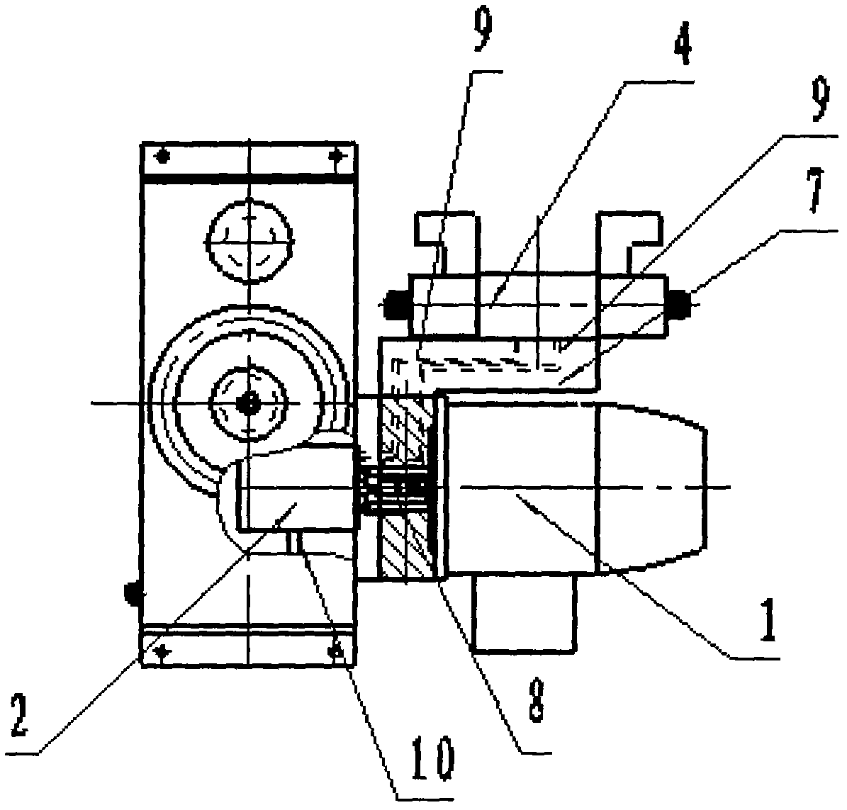
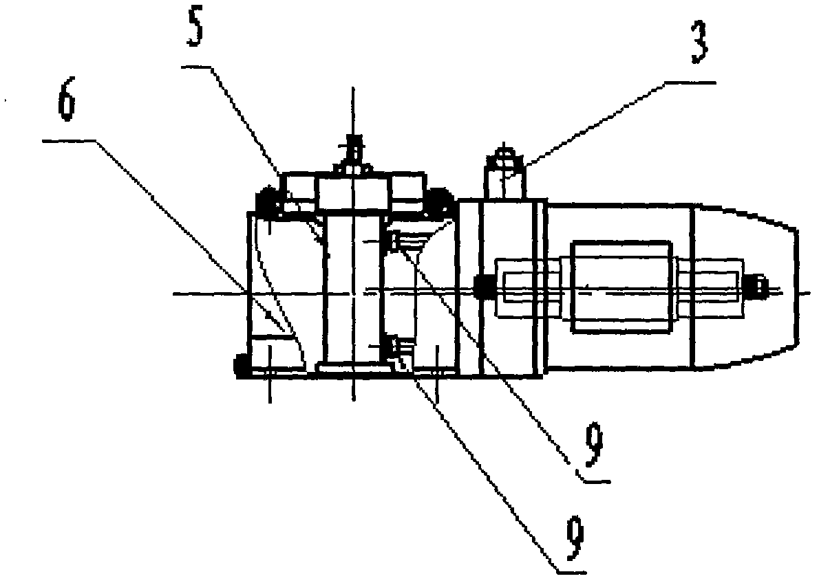
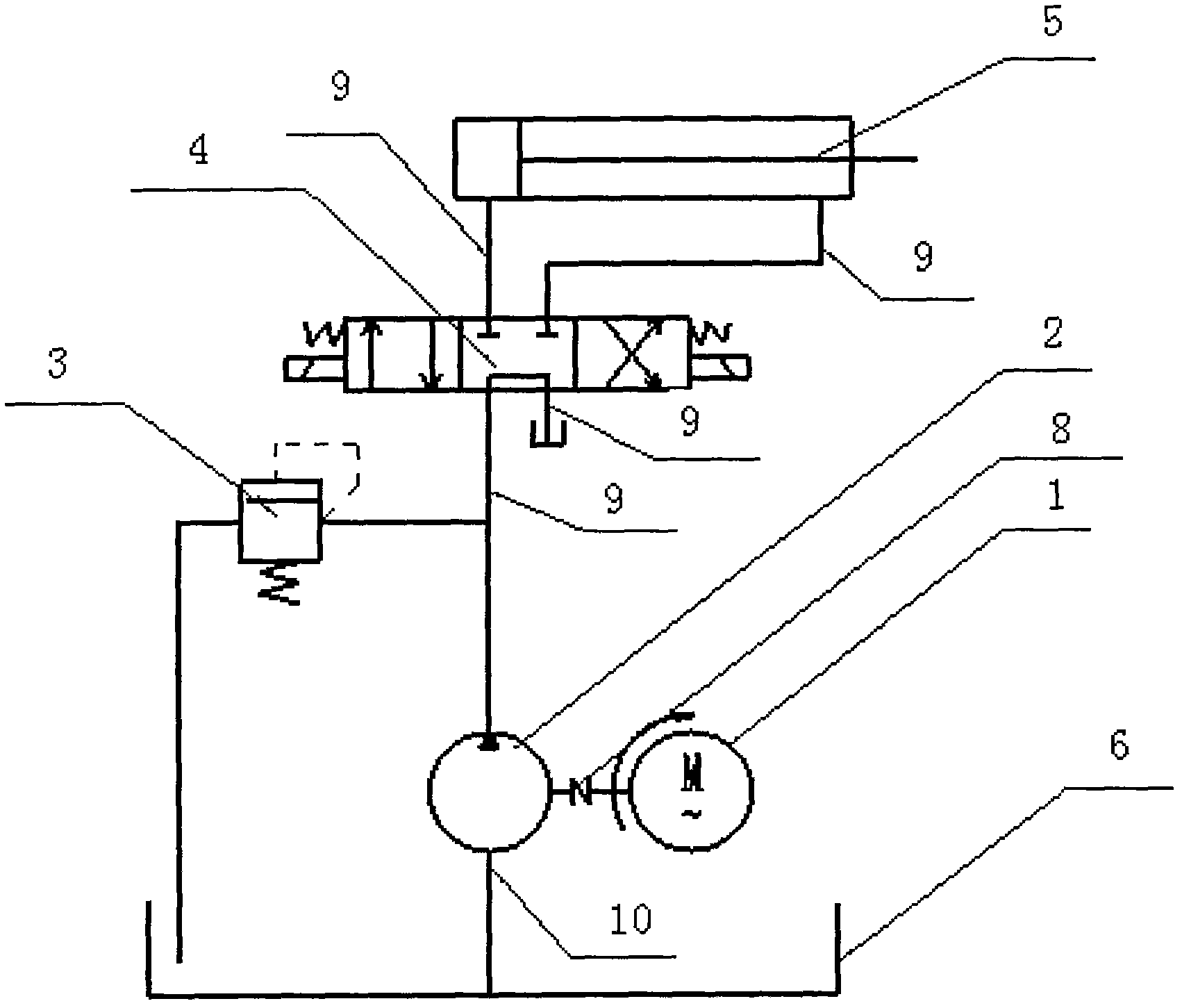
[0013] see figure 1 , figure 2 and image 3 , a driving device for a pallet stopper in an aviation building, comprising a motor 1, an oil pump 2, an overflow valve 3, an electromagnetic reversing valve 4, an oil cylinder 5, an oil tank 6, a valve seat 7, the shaft of the motor 1 and the The shaft of the oil pump 2 is connected with the shaft coupling 8; the oil pump 2 is connected with the oil tank 6 through the oil pipe 10, and the oil pump 2 is connected with the pressure of the overflow valve 3 and the electromagnetic reversing valve 4 through the oil pipe 9 respectively. The electromagnetic reversing valve 4 is an "M-type" reversing valve with a median function, and the electromagnetic reversing valve 4 is provided with two pressure oil outlets, and the two pressure oil outlets are The oil pipe 9 is respectively connected with the rod chamber and the rodless chamber of the oil cylinder 5. The electromagnetic reversing valve 4 is provided with an oil return port, and the...


PUM


Abstract

The invention discloses an aviation building tray stopper driving device. The aviation building tray stopper driving device comprises a motor, an oil pump, an overflow valve, an electromagnetic reversing valve, an oil cylinder, an oil tank and a valve seat, wherein a shaft of the motor is connected with a shaft of the oil pump through a shaft coupler; the oil pump is connected with the oil tank through an oil pipe; the oil pump is connected with the pressure oil inlets of the overflow valve and the electromagnetic reversing valve respectively through the oil pipe; the electromagnetic reversing valve is provided with two pressure oil outlets; the two pressure oil outlets are connected with a rod cavity and a rodless cavity of the oil cylinder through the oil pipe; the electromagnetic reversing valve is provided with an oil return opening; and the oil return opening is connected with the oil tank through the oil pipe. The aviation building tray stopper driving device has the advantages of light weight, small volume, simple structure, attractive and elegant appearance, quick response, locking at a fixed position and insusceptibility to damage.

Description

Technical field: [0001] The invention relates to a driving device, in particular to a driving device for a pallet stopper in an aviation building. Background technique: [0002] In the prior art, the airport pallet transportation mainly relies on manual sorting, and the automation level is low. In order to improve the transportation capacity of passengers' luggage and cargo at the airport. At present, most of the aviation building pallet stoppers are used in the airport passenger luggage pallet conveying line. The empty pallets are diverted and concentrated along different conveyor belts through the rising and falling of the aviation building pallet stopper, which is a good choice for the transportation of fast take-off and landing aircraft passenger luggage. Good material preparation. At present, the drive mechanism for rising and falling through the pallet stopper in the aviation building adopts a mechanical drive device, and its disadvantages are: ①, poor quick response...

Claims


Application Information

Patent Timeline
Patent Type & Authority Applications(China)
IPC IPC(8): B65G43/00
Inventor 仇九桃汤明风吴加国李庆和陆加和
Owner 江苏海陵机械有限公司
Learn More