Piezoelectric resonator element, piezoelectric device, and electronic apparatus
A piezoelectric vibrating piece and piezoelectric device technology, applied in electrical components, impedance networks, etc., can solve the problems of vibration leakage of the vibrating arm, difficulty in obtaining piezoelectric vibrating pieces of the vibrating arm, etc.
- Summary
- Abstract
- Description
- Claims
- Application Information
AI Technical Summary
Problems solved by technology
Method used
Image
Examples
no. 1 Embodiment approach
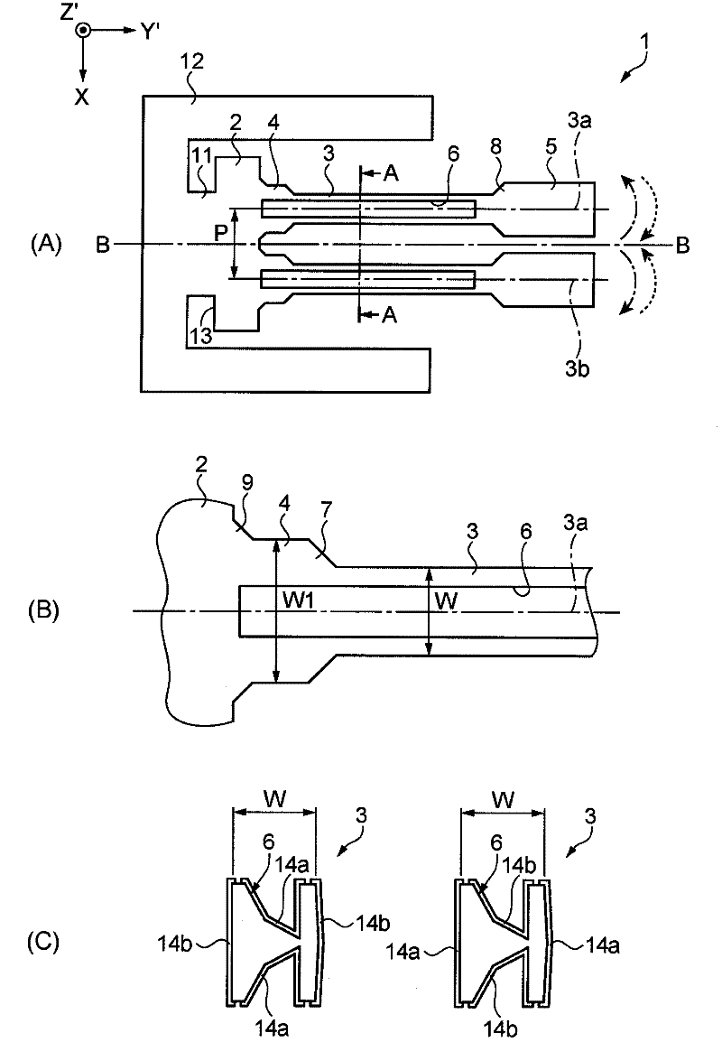
[0069] Below, refer to figure 1 The first embodiment will be described.
[0070] figure 1 (A) is a schematic plan view showing the crystal vibrating piece in the first embodiment. figure 1 (B) is, figure 1 (A) Partial enlarged view. figure 1 (C) for, along figure 1 Cross-sectional view of line A-A in (A).
[0071] Such as figure 1 Shown in (A), the crystal vibrating plate 1 has: the Z axis as the optical axis of the crystal column; the X axis as the electric axis perpendicular to the Z axis; the Y axis as the mechanical axis perpendicular to the X axis, and the crystal The vibrating piece 1 is cut from a crystal Z plate along a plane relative to the X-Y plane in directions around the X axis when viewed from the intersection point (coordinate origin) of the X axis and the Y axis A plane inclined at an angle of 0° to 5°. Such as figure 1 As shown, the width direction of the base part 2 is the X axis, the length direction of the vibrating arm part 3 is the Y' axis ...
no. 2 Embodiment approach
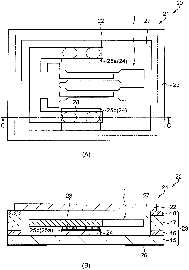
[0103] Below, refer to image 3 A second embodiment will be described.
[0104] The crystal device in the second embodiment uses figure 1 In the crystal vibrators of the crystal vibrating piece shown in the first embodiment, the same configurations are assigned the same reference numerals and descriptions of the configurations are omitted.
[0105] image 3 (A) is a schematic plan view showing the crystal resonator in the second embodiment. image 3 (B) for, along image 3 Cross-sectional view of line C-C in (A).
[0106] The crystal resonator in the second embodiment differs from the crystal vibrating piece in the first embodiment in that it includes a case for accommodating the crystal vibrating piece.
[0107] Such as image 3 As shown, the crystal vibrator 20 includes a crystal vibrating piece 1 and a case 21 . The crystal vibrating piece 1 is accommodated in the casing 21 in an airtight state. The casing 21 includes a base 23 and a cover 22 .
[0108] The base 23 ...
no. 3 Embodiment approach
[0121] Below, refer to Figure 4 A third embodiment will be described.
[0122] The crystal device of the third embodiment uses figure 1 In the crystal oscillator of the crystal vibrating piece shown in the first embodiment, the same configurations are assigned the same reference numerals and descriptions of the configurations are omitted.
[0123] The crystal oscillator in the third embodiment differs from the crystal resonator in the second embodiment in that it has a drive circuit electrically connected to the crystal resonator to drive the crystal resonator.
[0124] Such as Figure 4 As shown, the crystal oscillator 30 includes a crystal vibrating piece 1 , a case 21 and a drive circuit 31 . The crystal vibrating piece 1 and the driving circuit 31 are housed in the casing 21 in an airtight state. The casing 21 includes a base 23 and a cover 22 .
[0125] The base 23 includes a laminated substrate 34 . On the base substrate 15 , laminated substrates 34 , 16 , and 17...
PUM
 Abstract
Description
Claims
Application Information
 - R&D Engineer
- R&D Manager
- IP Professional
- Industry Leading Data Capabilities
- Powerful AI technology
- Patent DNA Extraction
Browse by: Latest US Patents, China's latest patents, Technical Efficacy Thesaurus, Application Domain, Technology Topic, Popular Technical Reports.
© 2024 PatSnap. All rights reserved.Legal|Privacy policy|Modern Slavery Act Transparency Statement|Sitemap|About US| Contact US: help@patsnap.com


