
Presser foot for sewing machine

A sewing machine and presser foot technology, which is applied in the field of sewing machine presser feet, can solve the problems that the fabric control device cannot be applied to various types of sewing machines, etc., and achieve the effect of easy material, preventing thread skipping, and easy manufacturing process

Active Publication Date: 2010-09-29
积家国际株式会社
View PDF7 Cites 2 Cited by
  • Summary
  • Abstract
  • Description
  • Claims
  • Application Information

AI Technical Summary

Problems solved by technology

Fabric control devices include such sensors and actuators and are therefore only used in very expensive sewing machines
Therefore, the fabric control device cannot be applied in various styles of sewing machines

Method used


Image

  • Presser foot for sewing machine
  • Presser foot for sewing machine
  • Presser foot for sewing machine

Examples


Embodiment Construction

[0078] Hereinafter, a first embodiment of the presser foot 1 for a sewing machine disclosed herein will be described with reference to the drawings. In the following description, the up and down directions are vertical directions that coincide with the moving direction of the sewing needle 6 . The front and rear directions correspond to the feeding direction of the processing material in the sewing machine. The left and right sides in the drawings correspond to the forward and backward directions, respectively.

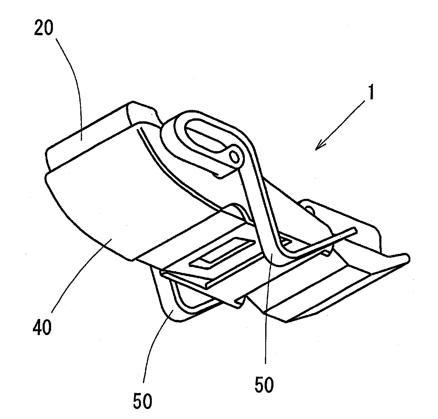
[0079] figure 1 is a perspective view of the presser foot 1 according to the first embodiment. The presser foot 1 includes a main body 20 , a restricting member 40 for restricting vertical movement of a processed material, and two leaf springs serving as restricting portions (elastic members) 50 attached to the restricting member 40 . The vertical movement of the processed material resembles an undulating flag and is henceforth referred to as "fluttering". Therefo...


PUM


Abstract

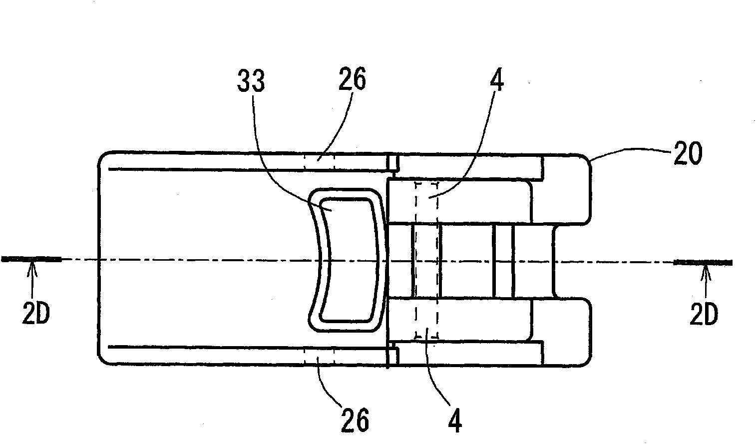
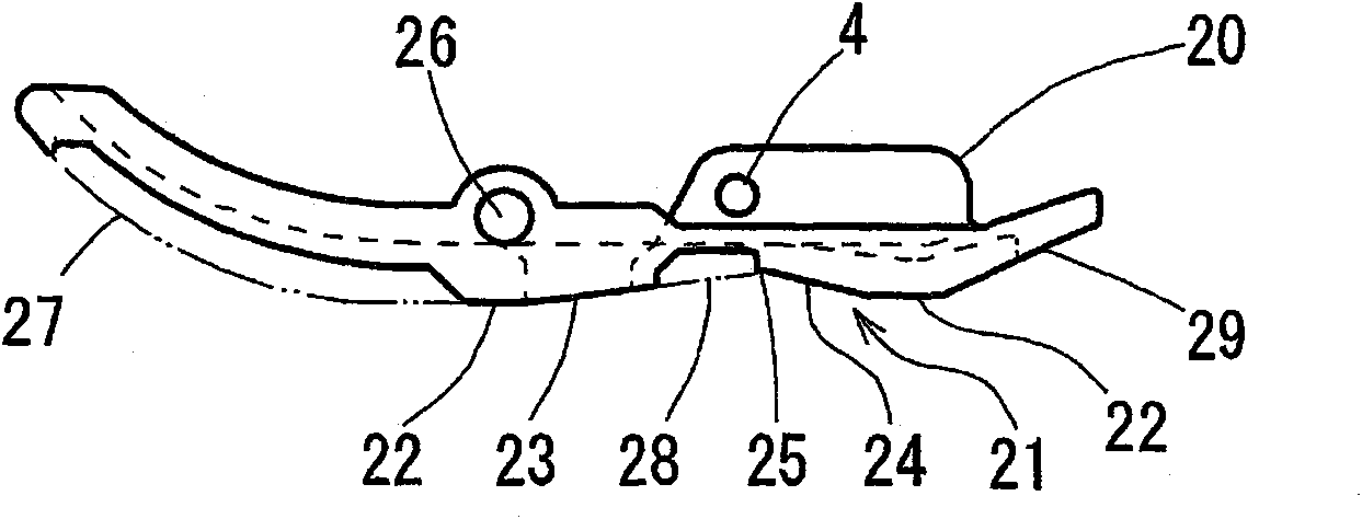
A presser foot (1) for a sewing machine includes a main body (20) rotatably attached to a presser holder (2) via a pivot shaft (4) and having a needle receiving hole (33), and a restriction member (40) rotatbly attached to the main body (20), wherein the restriction member (40) includes a restriction portion (50), which protrudes downward from a bottom face (21) of the main body (20) to press a work material to thereby restrict a movement of the work material when a stepped portion (10) of the work material comes in contact with the presser foot (1).

Description

technical field [0001] The present disclosure relates to a presser foot for a sewing machine, which presses a stepped portion of a processing material to restrain the processing material from moving unintentionally. Background technique [0002] As shown in FIG. 32 , a known presser foot 60 for a sewing machine includes a bottom surface 61 having a flat surface, a front presser foot portion 64 and a rear presser foot portion 67 . A needle receiving hole 62 is formed in the middle of the bottom surface 61 . The presser foot 60 is configured such that the bottom surface 61 reliably presses the processing material (fabric), thereby preventing the processing material from moving vertically along with the vertical movement of the sewing needle (such vertical movement of the processing material is similar to an undulating flag, Hence the name "flutter"). For example, as shown in Figure 33, in the case of cutting the edge of trousers or sewing straps, when the step portion 10 com...

Claims


Application Information

Patent Timeline
IPC IPC(8): D05B29/06
CPCD05B29/08
Inventor 吉田宪司
Owner 积家国际株式会社
Learn More