
led car headlights

A technology for automobile headlights and lamp sockets, which is applied in the directions of damage prevention measures for lighting devices, cooling/heating devices for lighting devices, lighting and heating equipment, etc. Large temperature difference in structure, shadows and other problems, to achieve good heat dissipation, improve luminous efficiency, and save costs

Inactive Publication Date: 2011-12-07
王宁军
View PDF0 Cites 1 Cited by
  • Summary
  • Abstract
  • Description
  • Claims
  • Application Information

AI Technical Summary

Problems solved by technology

However, there is a big problem in the practical application of LEDs, that is, the heat dissipation problem. The heat dissipation problem has always been the bottleneck in the LED application, and it has not been solved well for a long time. This problem is also a worldwide problem.
The gap between the light source module and the heat dissipation structure (radiator) is filled with thermally conductive silver glue and thermal paste, so there is still a certain thermal resistance between the light source module and the heat dissipation structure (radiator), which leads to The large temperature difference between the light source module and the heat dissipation structure cannot completely solve the heat conduction problem. Because this method does not solve the heat conduction and heat dissipation problems well, the LED cannot reach a large power value, making the brightness and photoelectricity of the LED conversion rate is too low
Moreover, due to the separate installation of single and multiple light source modules, the light uniformity and discs are not ideal, and there are shadows

Method used


Image

  • led car headlights
  • led car headlights
  • led car headlights

Examples


Embodiment 1

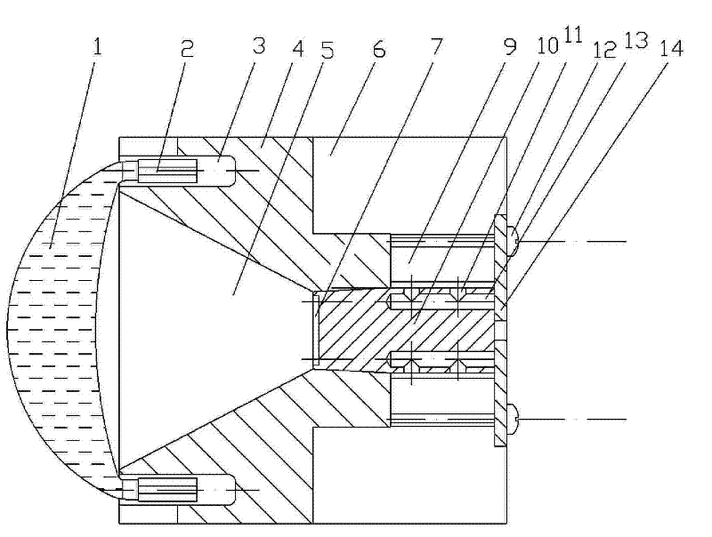
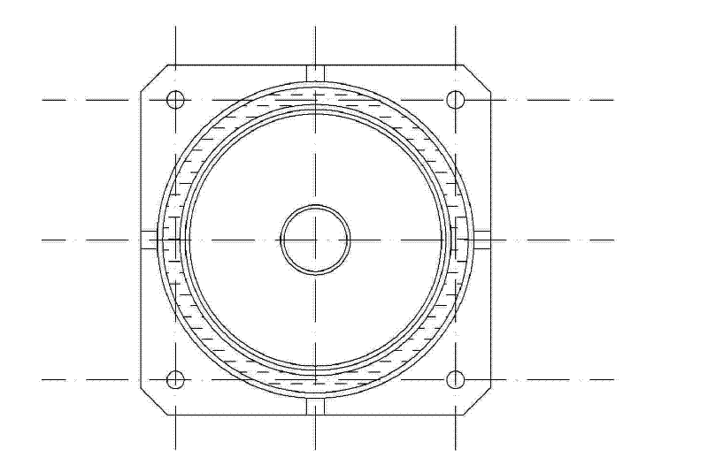
[0037] Such as Figure 1~4 Shown, a kind of LED automobile headlight is characterized in that, comprises lamp holder 4, cooling rod 10, lens 1 and LED chip 7;

[0038] The front end of the lamp holder 4 has a conical cavity 5 used as a lamp bowl, the large end face of the conical cavity 5 is on the front face of the lamp holder 4; a through hole, the through hole communicates with the conical cavity;

[0039] The front end surface of the lamp holder 4 is provided with an annular groove 3, the lens 1 covers the large end of the conical cavity 5, and the edge portion 2 of the lens is inserted into the annular groove 3;

[0040] The front end of the heat dissipation rod 10 is inserted into the through hole; the LED chip 7 is directly arranged on the front end surface of the heat dissipation rod 8; The overall shape of the automobile headlight is a cuboid whose front end is a square.

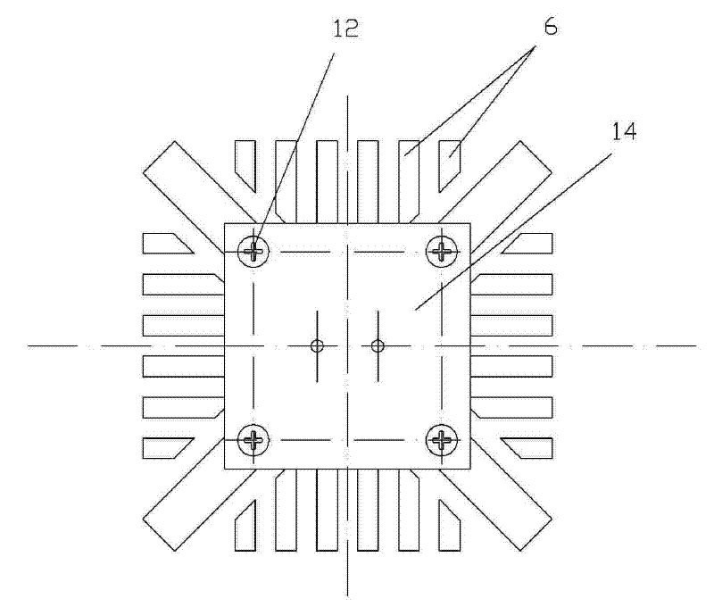
[0041] The rear end of the lamp holder 4 is provided with a plurality of cooling fins 6, and ...

Embodiment 2

[0048] Such as Figure 5-6 As shown, the overall shape of the LED automobile headlight is cylindrical. All the other structures are the same as in Example 1.


PUM


Abstract

The invention discloses an LED automobile headlamp characterized by comprising a lamp holder, a heat-radiating rod, a lens and an LED chip, wherein the front end of the lamp holder is provided with a circular table-shaped cavity used as a lamp bowl, and the center of the back end of the lamp holder is provided with a through hole; an annular groove is arranged on the front end of the lamp holder, and the edge of the lens is inserted in the annular groove; the front end of the heat-radiating rod is inserted in the through hole; the LED chip is directly arranged on the front end face of the heat-radiating rod; and the back end of the lamp holder is provided with a plurality of heat-radiating fins distributed around the back end of the heat-radiating rod, a first air chamber is formed between the heat-radiating fins and the back end of the heat-radiating rod, and the back end of the lamp holder is provided with a cover plate which is positioned on the back end face of the heat-radiating rod in a contact mode. The invention skillfully designs a heat-radiating mechanism formed by combining a squid body with bee holes through utilizing the principle of the bionics and solves the problems of heat radiation and application of the LED headlamp.

Description

technical field [0001] The invention relates to an LED automobile headlight, in particular to an LED automobile headlight with an integrated heat dissipation mechanism. Background technique [0002] In recent years, as the luminous efficiency of LED has been increased hundreds of times and the cost has dropped sharply, major global lighting manufacturers have successively joined in LED light source and market development. The United States, Japan, Europe and Taiwan Province of China have all launched semiconductor lighting plans. , our country is no exception. However, LEDs have a big problem in practical applications, that is, heat dissipation. The heat dissipation problem has always been a bottleneck in LED applications, and has not been solved well for a long time. This problem is also a worldwide problem. However, the application of high-power LEDs in the lighting field has just begun. There are many products, but there are many defects. In the final analysis, there is ...

Claims


Application Information

Patent Timeline
Patent Type & Authority Patents(China)
IPC IPC(8): F21S8/10F21V19/00F21V5/04F21V17/10F21V29/00F21V15/02F21W101/10F21Y101/02F21V29/508F21V29/76F21V29/83
Inventor 王宁军
Owner 王宁军
Learn More